Usb led, Pwr led, Invert/non-invert switch (s1) – Measurement Computing USB-ERB24 User Manual
Page 16: Usb led -2, Pwr led -2, Invert/non-invert switch (s1) -2
USB-ERB24 User's Guide
Functional Details
USB LED
The
USB
LED indicates the communication status of the USB-ERB24. It uses up to 5 mA of current and cannot
explains the USB LED function.
Table 3-2. USB LED Illumination
USB LED
illumination
Indication
Steady green
The USB-ERB24 is connected to a computer or external USB hub.
Pulsing green
Initial communication is established between the USB-ERB24 and the computer, or data is being
transferred.
PWR LED
The USB-ERB24 incorporates an on-board voltage supervisory circuit that monitors the external 9 V power. If
the input voltage falls outside of the specified range, the
PWR
LED shuts off.
the PWR LED.
Table 3-3. PWR LED Illumination
PWR LED
illumination
Indication
Steady green
External power is supplied to the USB-ERB24.
Off
Power is not supplied by the external supply, or a power fault has occurred. A power fault occurs
when the input power falls outside of the specified voltage range of the external supply
(6.0 V to 12.5 V).
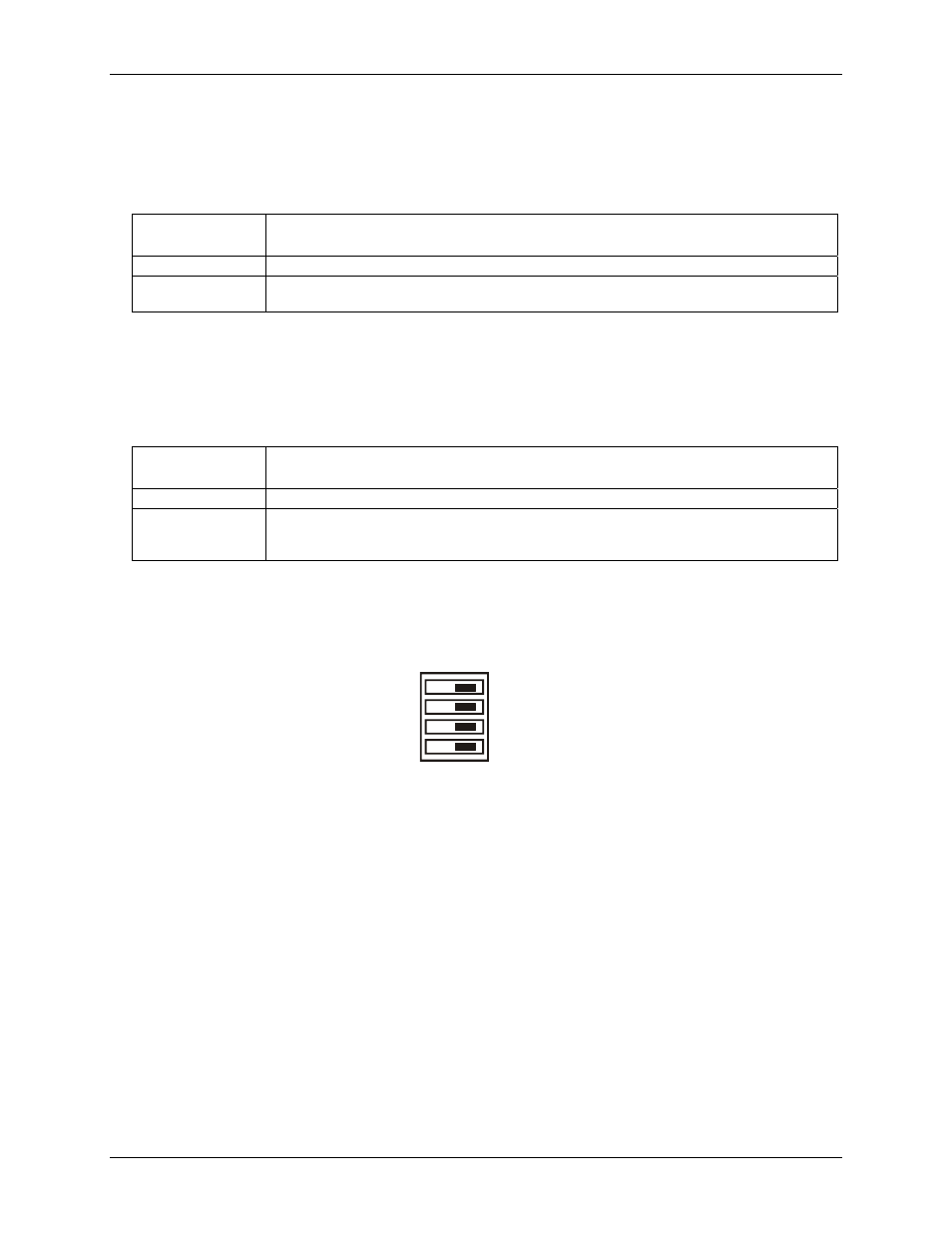
Invert/non-invert switch (S1)
The Invert/non-invert switch (S1) sets the relay control logic per relay bank to either inverted or non-inverted.
By default, switch S1 is configured for non-invert (see
).
Figure 3-2. Switch S1 default configuration
NON-INVERT
INVERT
S1
CL
CH
A
B
The switch labeled
A
configures relays 1 through 8, the switch labeled
B
configures relays 9 through 16, the
switch labeled
CH
configures relays 17 through 20, the switch labeled
CL
configures relays 21 through 24.
NON-INVERT
: when "0" is written or read back via the USB bus, the relays are not energized.
INVERT
: when "0" is written or read back via the USB bus, the relays are energized.
Switch settings do not affect the power-on condition. Use InstaCal to read the current logic setting for each
module group.
3-2