Power source jumper jp2, Usb led, Pwr led – Measurement Computing USB-DIO96H-50 User Manual
Page 12: Pin header connectors
USB-DIO96H/50 User's Guide
Functional Details
12
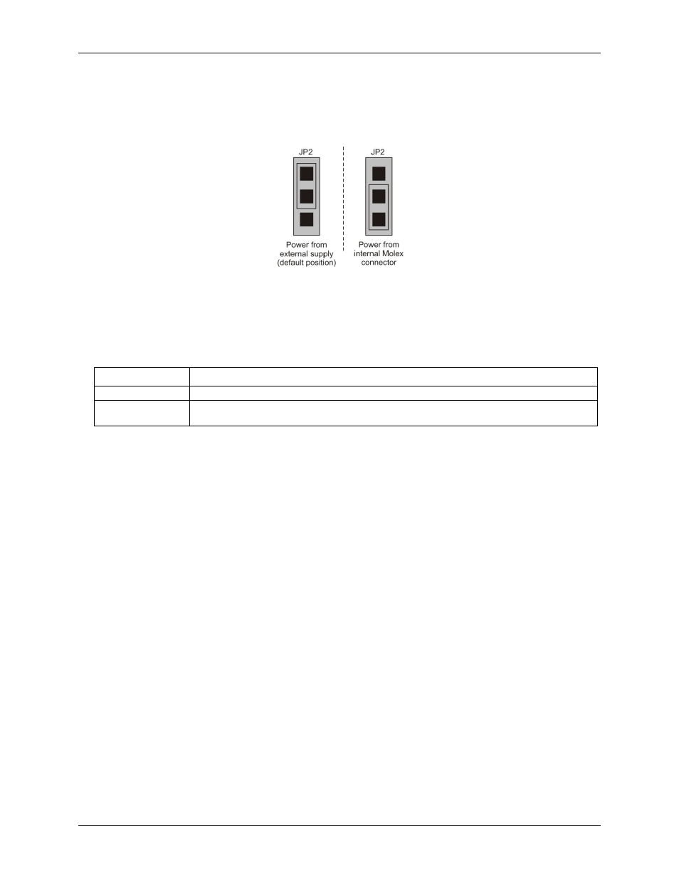
Power source jumper JP2
The power source jumper is labeled
JP2
on the board. Use this jumper to configure the USB-DIO96H/50 to use
either the external power connector (
POWER IN
) or the internal Molex connector. Figure 5 shows the jumper in
each configuration mode.
Figure 5. JP2 configuration modes
USB LED
The
USB
LED indicates the communication status of the USB-DIO96H/50. It uses up to 5 mA of current and
cannot be disabled. The table below explains the function of the
USB
LED.
USB LED illumination
LED Illumination
Indication
Steady green
The USB-DIO96H/50 is connected to a computer or external USB hub.
Continuous blink
Initial communication is established between the device and the computer, or data is being
transferred.
PWR LED
The
PWR
LED illuminates when external power is supplied. The USB-DIO96H/50 incorporates an on-board
voltage supervisory circuit that monitors the external power supply. The
PWR
LED does not light under the
following circumstances:
when the input power falls below +4.1 V
when the input power goes above +5.6 V
50-pin header connectors
The USB-DIO96H/50 has two 50-pin connectors labeled
P1
and
P2
.
Connector P1 provides the following connections:
48 DIO connections (
FIRSTPORTA Bit 0
through
SECONDPORTC Bit 7
)
one ground connection (
GND
)
one power connection (
+5V
)
Connector P2 provides the following connections:
48 DIO connections (
THIRDPORTA Bit 0
through
FOURTHPORTC Bit 7
)
one ground connection (
GND
)
one power connection (
+5V
)
Each digital port group is divided into two 8-bit ports and two 4-bit ports, and is a discrete emulation of 82C55
mode zero operation. You can configure each port independently for either input or output.