Functional details, Internal components, Usb connector – Measurement Computing USB-DIO96H-50 User Manual
Page 11: External power connector, Molex connector, Chapter 3
11
Chapter 3
Functional Details
Internal components
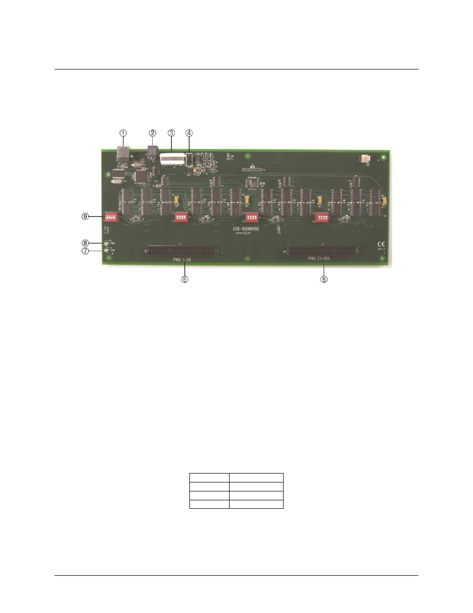
The USB-DIO96H/50 components are shown in Figure 4.
1
USB connector
4
Power source jumper JP2
7
USB LED
2
External power connector
5
P2 connector
– pins 52 to 100
8
PWR LED
3
Molex connector
6
P1 connector
– pins 1 to 50
9
Pull-up/down DIP switches
(Port 1 through Port 4)
Figure 4. USB-DIO96H/50 components
USB connector
Connect the supplied USB cable between the device and the USB port on the computer (or USB hub connected
to the computer). This connector is labeled
USB IN
on the enclosure and
J1
on the board.
External power connector
The external power connector is labeled
POWER IN
on the enclosure and
P5
on the board. Connect the
POWER
IN
connector to the supplied +5 V external power supply (PS-5V3AEPS). When running at full load, the device
draws 2.6 A from the supply.
Molex connector
The internal Molex connector is labeled
P6
on the board. Remove the device enclosure to access this connector.
Internal power connector pinout
Pin 1
5V
Pin 2
GND
Pin 3
GND
Pin 4
NC (no connect)