Counter, Memory, Microcontroller – Measurement Computing USB-2408 Series User Manual
Page 29
USB-2408 Series User's Guide
Specifications
29
Counter
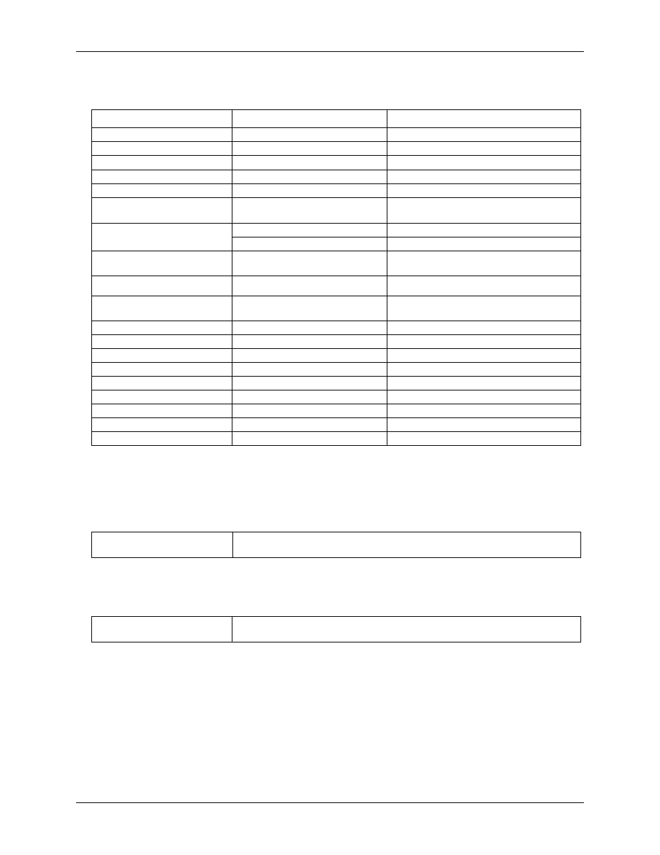
Table 20. CTR specifications
Parameter
Conditions
Specification
Pin name
CTR0, CTR1
Number of channels
2 channels
Resolution
32-bits
Counter type
Event counter
Input type
Schmitt trigger, rising edge triggered
Input source
CTR0 (pin 44)
CTR1 (pin 42)
Counter read/writes rates
(software paced)
Counter read
System dependent, 500 reads per second.
Counter write
System dependent, 500 writes per second.
Input characteristics
Each CTRx input pin
562 kΩ pull-up resistor to +5 V, 10 kΩ series
resistor
Input voltage range
±15 V max
Max input voltage range
CTR0,CTR1 relative to AGND
and DGND (Note 7)
±20 V max (power on/off)
Input high voltage
1.3 V min, 2.2 V max
Input low voltage
1.5 V max, 0.6 V min
Schmitt trigger hysteresis
0.4 V min, 1.2 V max
Input bandwidth (–3 dB)
1 MHz
Input capacitance
25 pf
Input leakage current
±120 nA@5 V, ±1.6 mA@±15 V
Input frequency
1 MHz, max
High pulse width
500 ns, min
Low pulse width
500 ns, min
Note 7:
DGND pins are recommended for use with counter input pins. The DGND and AGND are common
and are isolated from earth ground.
Memory
Table 21. Memory specifications
EEPROM
4096 bytes isolated micro reserved for sensor configuration
256 bytes USB micro for external application use
Microcontroller
Table 22. Microcontroller specifications
Type
One high-performance 8-bit RISC microcontroller with USB interface (non-isolated)
One high-performance 16-bit RISC microcontroller for measurements (isolated)