Internal pull-up/pull-down capability – Measurement Computing USB-2408 Series User Manual
Page 17
USB-2408 Series User's Guide
Functional Details
17
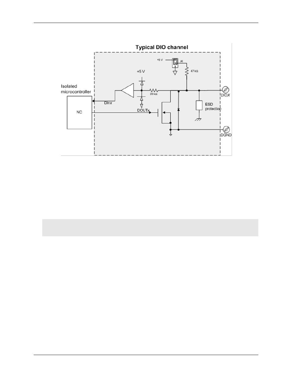
Figure 10 shows a typical DIO connection.
Figure 10. Digital output connection example
The figure represents connections for one channel. The other seven channels are connected in the same manner.
The maximum sink current is 150 mA per 8-channel bank, or if all eight channels are used, 18 mA (maximum)
per channel.
Internal pull-up/pull-down capability
Unconnected inputs are pulled high by default to 5 V using 47 kΩ resistors through jumper
J6
on the circuit
board. The pull-up/pull-down voltage is common to all 47 kΩ resistors. Complete the following steps to
configure these inputs.
Caution! The discharge of static electricity can damage some electronic components. Before removing the
USB-2408 Series device from its housing, ground yourself using a wrist strap or touch the
computer chassis or other grounded object to eliminate any stored static charge.
To open the case and set the J6 jumper, do the following.
1. Turn the device over and rest the top of the housing on a flat, stable surface.
2. Peel off the four rubber feet on the bottom of the device to access the screws.
3. Remove the four screws from the bottom of the device.
4. Hold both the top and bottom sections together, turn the device over and rest it on the surface, then
carefully remove the top section of the case to expose the circuit board.
5. Configure jumper
J6
for either pull-up (pins 1-2) or pull-down (pins 2-3). The jumper is configured by
default for pull-up. Figure 11 shows the location of the jumper on the board.