Channel-gain queue, Digital i/o, Pull-up/down configuration – Measurement Computing USB-1616FS User Manual
Page 16: Counter input, Trigger input
USB-1616FS User's Guide
Functional Details
16
Channel-gain queue
The channel-gain queue feature allows you to configure a different gain setting for each channel. The gain
settings are stored in a channel-gain queue list that is written to local memory on the device.
The channel-gain queue list can contain up to 16 unique elements. The channel list must be in increasing order.
An example of an 8-element list is shown in the following table.
Sample channel-gain queue list
Element
Channel
Range
0
CH0
BIP10V
1
CH1
BIP5V
2
CH2
BIP10V
3
CH3
BIP1V
4
CH4
BIP2V
5
CH5
BIP10V
6
CH6
BIP1V
7
CH7
BIP5V
Carefully match the gain to the expected voltage range on the associated channel or an over range condition
may occur. Although this condition does not damage the device, it does produce a useless full-scale reading,
and can introduce a long recovery time due to saturation of the input channel.
Digital I/O
You can connect up to eight digital I/O lines to the screw terminals labeled
DIO 0
to
DIO 7
. Each digital channel
is individually configurable for input or output.
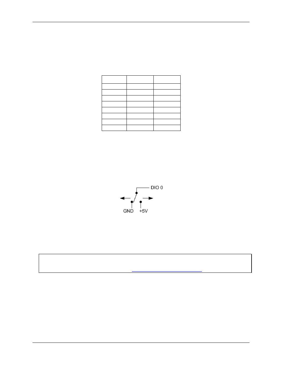
The digital I/O terminals can detect the state of any TTL-level input. Refer to the schematic shown in Figure 5.
Figure 5. Schematic showing switch detection by digital channel DIO0
If you set the switch to the +5 V input, DIO 0 reads TRUE (1). When set to GND, DIO 0 reads FALSE (0).
Pull-up/down configuration
All digital I/O lines are pulled up by default to USB +5V with a 47 kΩ resistor. To configure for pull-down, the
board must be modified at the factory.
For more information on digital signal connections
For general information regarding digital signal connections and digital I/O techniques, refer to the Guide to
Signal Connections (available on our web site
Counter input
The CTR terminal (
CTR
) is a TTL level input to a 32-bit event counter. The internal counter increments when
the TTL level transitions from low to high. The counter can count frequencies of up to 1 MHz.
Trigger input
The trigger terminal (
TRIG IN
) is an external digital trigger input. You can configure this terminal with software
for either rising (default) or falling edge.