Usb led, Pwr led, Screw terminals – Measurement Computing USB-1616FS User Manual
Page 14
USB-1616FS User's Guide
Functional Details
14
To supply external power, connect the
POWER IN
connector to the supplied +9 V external power supply
(CB-PWR-9V3A).
The
POWER OUT
connector lets you power additional daisy chained MCC USB Series devices from a single
external power supply. The C-MAPWR-x cable is available from MCC to connect additional MCC USB Series
devices.
USB LED
The
USB
LED indicates the communication status of the USB-1616FS. This LED uses up to 5 mA of current
and cannot be disabled. The table below explains the behavior of the USB LED.
USB LED Illumination
USB LED
Indication
Steady green
The USB-1616FS is connected to a computer or external USB hub.
Blinks continuously
Initial communication is established between the USB-1616FS and the computer, or data is
being transferred.
PWR LED
The USB-1616FS incorporates an on-board voltage supervisory circuit that monitors the USB VBUS (5V) and
the external 9 V power supply. If the input voltage falls outside of the specified ranges the
PWR
LED shuts off
(see table below).
PWR LED Illumination
PWR LED illumination
Indication
Steady green
USB +5 V power or +9 V external power is supplied to the device.
Off
Input power is not supplied, or a power fault has occurred. A power fault occurs when
the input power falls outside of the specified voltage range:
USB VBUS (+5 V):
4.75 V to 5.25 V
External power: (+9 V): 6.0 V to 12.5 V
Screw terminals
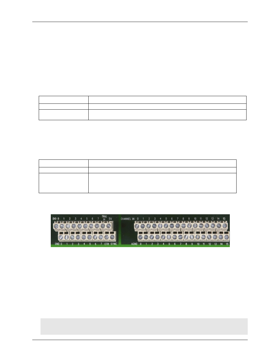
The device has two rows of screw terminals. Each row has 26 connections. Signal labels are shown in Figure 4.
Figure 4. USB-1616FS screw terminals
The screw terminals provide the following connections:
eight digital I/O terminals (
DIO 0
to
DIO 7
)
one external digital trigger terminal (
TRIG IN
)
one power terminal (
5V
)
eight ground terminals (
GND 0
to
7
)
one external event counter terminal (
CTR
)
one terminal for external clocking and multi-unit synchronization (
SYNC
)
16 analog input terminals (
CHANNEL IN 0 to 15
)
16 analog ground terminals (
AGND 0 to 15
)
Use 14 AWG to 30 AWG wire for your signal connections.
Caution! Keep the length of stripped wire at a minimum to avoid a short to the enclosure! When connecting
your field wiring to the screw terminals, use the strip gage on the terminal strip, or strip to 5.5 -
7.0 mm (0.215" to 0.275") long.