Measurement Computing PCI-DDA02/12 User Manual
Page 11
PCI-DDA02/12 User's Guide
Functional Details
11
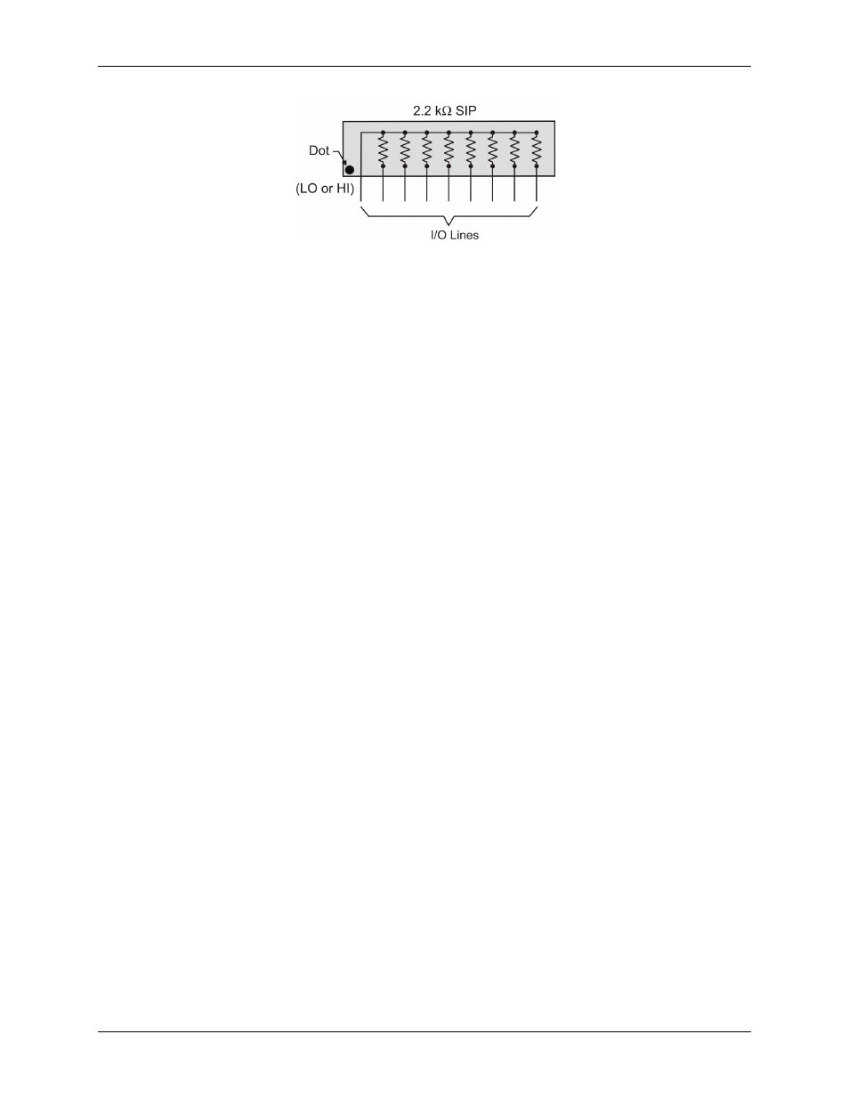
Figure 3. Eight-Resistor SIP Schematic
You can install the SIP as either pull-up or pull-down. At each location there are 10 holes in a line. One end of
the line is +5V, the other end is GND. They are marked
HI
and
LO
respectively. The eight holes in the middle
are connected to the eight lines of a port.
For a pull-up function per port, mount the SIP with the common pin (marked with a dot or line) in the
HI
position.
For a pull-down function per port, mount the SIP with the common pin in the
LO
position.
When installing pull-up and pull-down resistor SIP packs, we recommend using a 2.2 K, eight-resistor SIP
(MCC part number SP-K2.29C). You can substitute individual 2.2 kΩ resistors for the resistor SIPs, if required.