Configuring the pci-das-tc, Connecting the board for i/o operations, Connectors, cables – main i/o connector – Measurement Computing PCI-DAS-TC User Manual
Page 10: Pin out – main i/o connector
PCI-DAS-TC User's Guide
Installing the PCI-DAS-TC
10
3. To test your installation and configure your board, run the InstaCal utility you installed in the previous
section. Refer to the Quick Start Guide that came with your board for information on how to initially set up
and load InstaCal.
Configuring the PCI-DAS-TC
All hardware configuration options on the PCI-DAS-TC are software controlled. You can select some of the
configuration options using InstaCal, such as the thermocouple type, CJC on/off, voltage or thermocouple gain,
and temperature units. Once selected, any program that uses the Universal Library will initialize the hardware
according to these selections.
Connecting the board for I/O operations
Connectors, cables
– main I/O connector
The table below lists the board connector, applicable cable and compatible accessory equipment for the PCI-
DAS-TC board.
Board connector, applicable cable, and accessory equipment
Connector type
37-pin D-type
Compatible cable
C37FFS-x (Figure 2)
Compatible accessory product with the C37FFS-x
CIO-STA-TC screw terminal adapter board
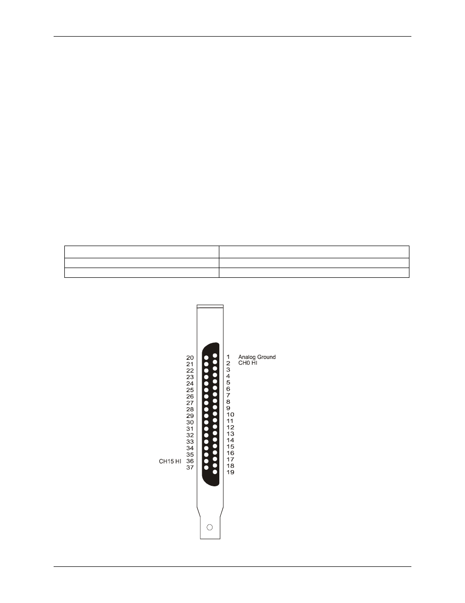
Pin out
– main I/O connector
None
CH14 HI
CH7 LO
CH13 LO
CH13 HI
CH11 LO
CH11 HI
CH9 LO
CH9 HI
CH7 HI
CH5 LO
CH5 HI
CH3 LO
CH3 HI
CHh1 LO
CH1 HI
CJC INPUT
+15V Isolated Voltage Source
CH15 LO
CH14 LO
Analog Ground
CH12 LO
CH12 HI
CH10 LO
CH10 HI
CH8 LO
CH8 HI
CH6 LO
CH6 HI
CH4 LO
CH4 HI
CH2 LO
CH2 HI
CH0 LO
Figure 1. 37-pin board connector