Ctr1 gate signal, Ctr1 out signal, Ctr2 clk signal – Measurement Computing PCI-DAS6013 User Manual
Page 27
PCI-DAS6013 and PCI-DAS6014 User's Guide
Functional Details
27
CTR1 GATE signal
You can use the CTR1 GATE signal for starting and stopping the counter, saving counter contents, etc. It is
polarity programmable and is available at the CTR1 GATE pin.
Figure 23 shows the minimum timing requirements for the CTR1 GATE signal.
Rising Edge Polarity
t
w
t
w
= 25 ns minimum
Falling Edge Polarity
Figure 23. CTR1 GATE signal timing
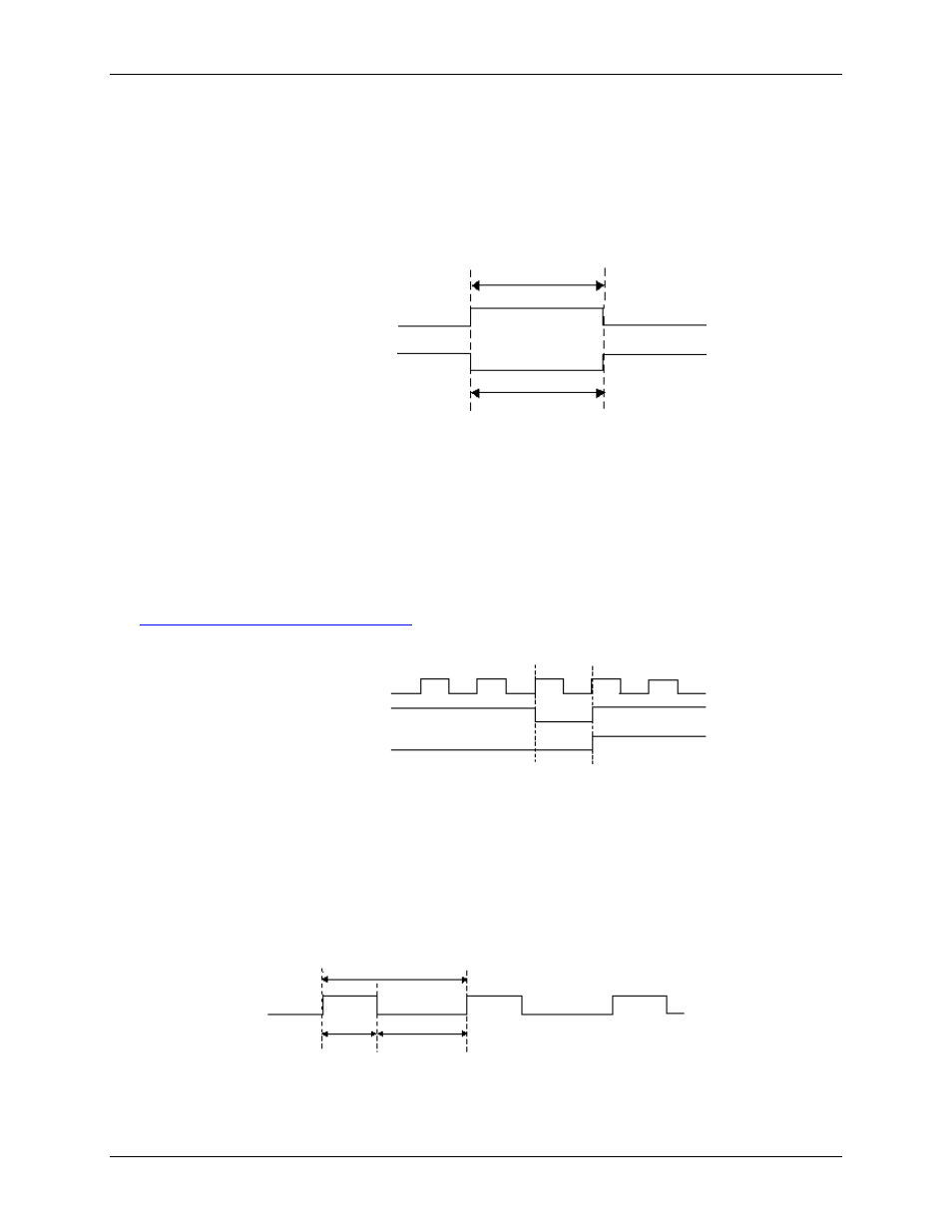
CTR1 OUT signal
This signal is present on the CTR1 OUT pin. The CTR1 OUT signal is the output of one of the two user’s
counters in an industry-standard 82C54 chip. Figure 24 shows the timing requirements for the CTR1 OUT
signal for counter mode 0 and mode 2.
For detailed information on counter operations, please refer to the data sheet on our web site at
CTR1 CLK
TC
CTR1 OUT (Mode 2)
CTR1 OUT (Mode 0)
Figure 24. CTR1 OUT signal timing
CTR2 CLK signal
The CTR2 CLK signal can serve as the clock source for independent user counter 2. It can be selected through
software at the CTR2 CLK pin rather than using the on-board 10 MHz or 100 kHz sources. It is also polarity
programmable. The maximum input frequency is 10 MHz. There is no minimum frequency specified. Figure 25
shows the timing requirements for the CTR2 CLK signal.
t
w-L
t
w-H
=15 ns minimum
t
w-H
t
p
=100 ns minimum
t
w-L
=25 ns minimum
Figure 25. CTR2 CLK signal timing