Daq signal timing, Scanclk signal, A/d start trigger signal – Measurement Computing PCI-DAS6013 User Manual
Page 20
PCI-DAS6013 and PCI-DAS6014 User's Guide
Functional Details
20
DAQ signal timing
The DAQ timing signals are:
SCANCLK
A/D START TRIGGER
A/D STOP TRIGGER
STARTSCAN
SSH
A/D CONVERT
A/D PACER GATE
A/D EXTERNAL TIMEBASE
A/D STOP
SCANCLK signal
SCANCLK is an output signal that may be used for switching external multiplexers. It is a 400 ns wide pulse
that follows the CONVERT signal after a 50 ns delay. This is adequate time for the analog input signal to be
acquired so that the next signal may be switched in. The polarity of the SCANCLK signal is programmable. The
default output pin for the SCANCLK signal is AUXOUT2, but any of the AUXOUT pins may be programmed
as a SCANCLK output.
CONVERT
SCANCLK
t
d
t
d
t
w
t
d
= 50 ns
t
w
= 400 ns
Figure 4. SCANCLK signal timing
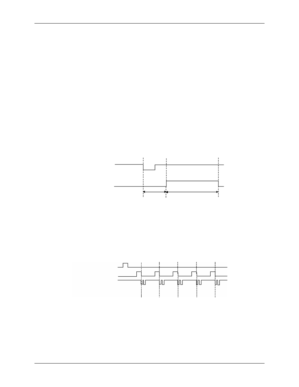
A/D START TRIGGER signal
Use the A/D START TRIGGER signal for conventional triggering (when you only need to acquire data after a
trigger event). Figure 5 shows the A/D START TRIGGER signal timing for a conventionally triggered
acquisition.
A/D Start Trigger
Start Scan
Convert
1
2
3
4
0
Scan Counter
Figure 5. A/D START TRIGGER
— Data acquisition example for conventional triggering
The A/D START TRIGGER source is programmable and may be set to any of the AUXIN inputs. The polarity
of this signal is also programmable to trigger acquisitions on either the positive or negative edge.
The A/D START TRIGGER signal is also available as an output and can be programmed to appear at any of the
AUXOUT outputs. See Figure 6 and Figure 7 for A/D START TRIGGER input and output timing
requirements.