Functional details, Pci-das1602/16 block diagram, Analog inputs – Measurement Computing PCI-DAS1602/16 User Manual
Page 16: Chapter 3, Two 16-bit analog outputs, Bits, high current digital i/o
15
Chapter 3
Functional Details
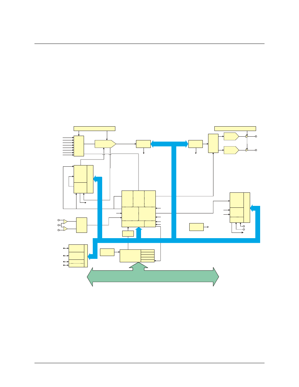
PCI-DAS1602/16 block diagram
The PCI-DAS1602/16 provides the following features:
16 single-ended or eight fully differential 16-bit analog inputs
Two 16-bit analog outputs
24-bits, high current digital I/O
Three 16-bit down counters
PCI-DAS1602/16 functions are illustrated in the block diagram shown here.
FIRSTPORTA
C
o
n
tr
o
l
FIRSTPORTA (7:0)
High-Drive DIO
8
PCI
CONTROLLER
BADR1
BADR2
BADR3
BADR4
Interrupt
Boot
EEPROM
ADC
Pacer
Control
Scan
&
Burst
Logic
HS
DAC
Control
Trigger
Control
DAC Pacer
Control
Decode/Status
Int
Ctl
Bus
Timing
EXT
PCR
10MHz
INT
XINT
Burst/Scan
XTRIG
CONTROLLER
FPGA
Analog
Trigger
Logic
TRIG_HI
Analog
Trigger
TRIG_LO
ADC
Pacer
CTR 2
CTR 1
Sample
Counter
CTR0
C
o
n
tr
o
l
Gain and Offset Autocal
INT
16-Bit, 200KHz
Mux
&
Gain
Analog In
16 CH S.E.
8 CH DIFF.
512 x 16
FIFO
Gain and Offset Autocal
DAC
Data
Control
D/A 0
D/A 1
512 X 16
FIFO
DAC
Pacer
CTR2
CTR1
ADC
Index
Counter
User
CTR 0
C
o
n
tr
o
l
Time Base
GATE
CLK
OUT
INT
XTRIG
Start EOC
DAC0
DAC1
16-Bit, 100KHz
16-Bit, 100KHz
INT
10MHz
LOCAL BUS
PCI BUS (5V, 32-BIT, 33MHZ)
FIRSTPORTB (7:0)
FIRSTPORTCH (3:0)
FIRSTPORTB
FIRSTPORTCH
INT
FIRSTPORTCL
FIRSTPORTCL (3:0)
Figure 3. PCI-DAS1602/16 functional block diagram
Analog inputs
The analog input mode is software-selectable for eight differential or 16 single-ended analog inputs. The board
offers a 200 kHz maximum sample rate in single and multichannel scans at any gain setting. A 512 sample
FIFO assures that data taken from the board is transferred into computer memory without the possibility of
missed samples. The board has an analog trigger input with software-selectable trigger levels and direction.