Analog signal conditioning and expansion, Digital signal conditioning – Measurement Computing PCI-DAS1602/16 User Manual
Page 15
PCI-DAS1602/16 User's Guide
Installing the PCI-DAS1602/16
14
Analog signal conditioning and expansion
ISO-RACK16/P – 16-channel isolation module mounting rack.
ISO-DA02/P – Two-channel, 5B module rack.
Details on these products are available at
Digital signal conditioning
The following digital signal conditioning products have 37-pin connectors. Use the DADP-5037 adaptor board
for connections to the C100FF-x cable's 50-pin connectors.
SSR-RACK24 – 24-position solid state relay rack. The DADP-5037 adaptor board is required.
SSR-RACK08 – Eight-channel solid state relay rack. The DADP-5037 with TN-MC78M05CT adaptor
board is required.
CIO-ERB24 – 24-channel electromechanical relay accessory for digital I/O boards. The DADP-5037
adaptor board is required.
CIO-ERB08 – Eight-channel electromechanical relay accessory for digital I/O boards. The DADP-5037
adaptor board is required.
Details on digital signal conditioning products are available at
Details on the DADP-5037 adapter board are available
at
Caution! Before connecting signals to the PCI-DAS1602/16, measure the voltage between ground at the
signal source and ground at the PC. If you measure >10 volts, do not connect the board to this
signal source, as you are beyond the usable input range of the board. Either adjust your grounding
system or add isolation signal conditioning to take useful measurements. A ground offset voltage
of more than 30 volts may damage the board and possibly your computer. An offset voltage much
greater than 30 volts will damage your electronics, and may be hazardous to your health.
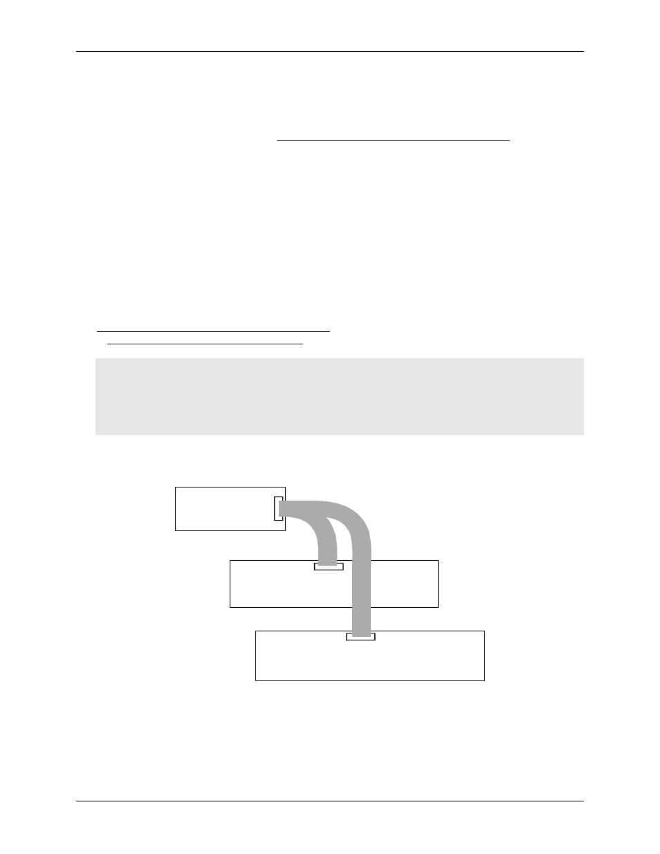
To terminate signals and route them into the PCI-DAS1602/16, use the SCB-50 signal connection box,
CIO-TERM100 screw terminal board, or two CIO-MINI50 screw terminal boards.
SCB-50, CIO-MINI50,
CIO-TERM100 or
analog signal conditioning
PCI-DAS1602/16
100-pin I/O connector
Analog I/O pins
1 to 50
Digital I/O pins
51 to 100
IN
IN
SCB-50, CIO-MINI50,
CIO-TERM100 or
digital signal conditioning
C100FF-x
Figure 2. Sample wiring configuration using the C100FF-x cable