Field wiring and signal termination, Screw terminal boards, Bnc connector interface boxes – Measurement Computing PCI-DAS1602/16 User Manual
Page 14
PCI-DAS1602/16 User's Guide
Installing the PCI-DAS1602/16
13
1
50
2
49
51
100
52
99
100
50
51
1
Key
Key
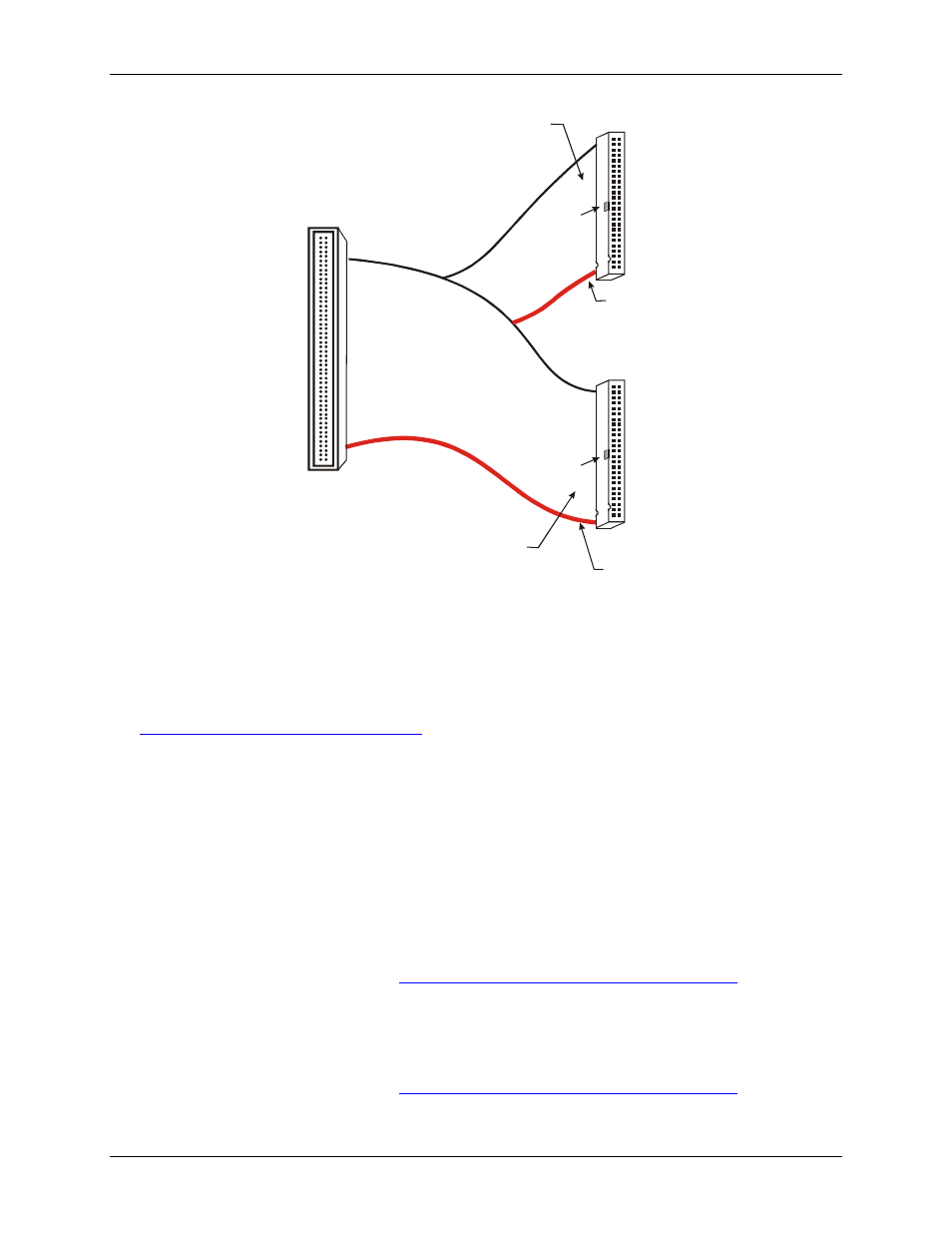
The red stripe
identifies pin # 1
The red stripe
identifies pin # 51
Cable is labeled
“Pins 51-100”
Cable is labeled
“Pins 1-50”
Field Wiring connections:
SCB-50
CIO-MINI50
CIO-MINI50/DST
CIO-TERM100/DST
BNC-16DI or BNC-16SE
ISO-RACK16/P or ISO-DA02/P
with the DADP-5037 adaptor board:
CIO-ERB08 or CIO-ERB24
SSR-RACK08 or SSR-RACK24
Connect to the board’s
100-pin I/O connector.
Pin 1 is indicated by an
arrow on the connector.
Figure 1. C100FF-x cable
The first 50-pin connector is used primarily for analog signals (pins 1-50 on the 100-pin connector). The
second 50-pin connector is used primarily for digital signals (pins 51-100 on the 100-pin connector). This
configuration minimizes noise in the analog signal lines, and greatly simplifies field wiring and connections to
external devices. You can purchase C100FF-x series cables from our web site at
Field wiring and signal termination
You can use the following MCC screw terminal boards to terminate field signals and route them into the PCI-
DAS1602/16 board using the C100FF-x cable:
Screw terminal boards
CIO-TERM100 – 100 pin, 16 x 4 screw terminal board.
CIO-MINI50 – 50-pin universal screw terminal accessory. Two boards are required.
SCB-50 – 50-conductor, shielded signal connection/screw terminal box providing two independent 50-pin
connections. One box is required.
Details on these products are availa
BNC connector interface boxes
BNC-16SE – 16-channel single-ended BNC connector box.
BNC-16DI – Eight-channel differential BNC connector box.
Details on these products are available at