Figure 2-3 – Measurement Computing PCI-DAS08 User Manual
Page 12
PCI-DAS08 User's Guide
Installing the PCI-DAS08
20
1
37
19
20
1
37
19
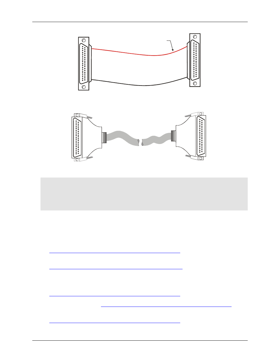
The red stripe
identifies pin # 1
Figure 2-2. C37FF-x cable
20
1
37
19
20
1
37
19
Figure 2-3. C37FFS-x cable
Caution! If either the AC or DC voltage is greater than 5 volts, do not connect the PCI-DAS08 to this signal
source. You are beyond the board's usable input range and will need to either adjust your
grounding system or add special isolation signal conditioning to take useful measurements. A
ground offset voltage of more than 7 volts may damage the PCI-DAS08 board and possibly your
computer. An offset voltage much greater than 7 volts will damage your electronics, and may be
hazardous to your health.
Field wiring, signal termination and signal conditioning
You can use the following MCC screw terminal boards to terminate field signals and route them into the PCI-
DAS08 board using the C37FF-x or C37FFS-x cable:
!
CIO-MINI37
– 37-pin screw terminal board. Details on this product are available at
.
!
SCB-37
– 37 conductor, shielded signal connection/screw terminal box that provides two independent 50-
pin connections. Details on this product are available at
MCC provides the following analog signal conditioning products for use with your PCI-DAS08 board:
!
ISO-RACK08
– Isolated 8-channel, 5B module rack for analog signal conditioning and expansion. Details
on this product are available on our web site at
.
!
CIO-EXP16
– 16-channel analog multiplexer board with on-board CJC sensor. Details on this product are
available on our web site at
!
CIO-EXP32
– 32-channel analog multiplexer board with on-board CJC sensor and 2 Gain amps. Details on
this product are available on our web site at
.
2-4