Single-ended configuration, Differential configuration – Measurement Computing miniLAB-1008 User Manual
Page 18
miniLAB 1008 User's Guide
Functional
Details
Single-ended configuration
When all of the analog input channels are configured for single-ended input mode, eight analog channels are
available. In single-ended mode, the input signal is referenced to signal ground (GND). The input signal is
delivered through two wires:
!
The wire carrying the signal to be measured connects to CH# IN.
!
The second wire connects to GND.
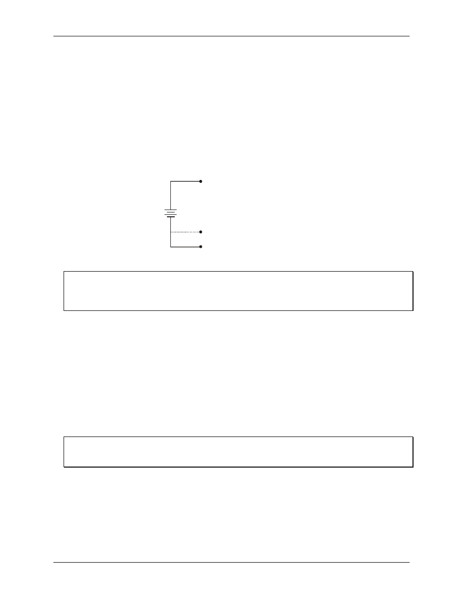
The input range for single-ended mode is ±10 V max, with a gain of 2. No other gains are supported in single-
ended mode.
Figure 3-4. Single-ended measurement connection
illustrates a typical single-ended measurement connection.
GND
CH0
CH1 (differential configuration)
1.5
+
-
Single-ended measurements using differential channels
To perform a single-ended measurement using differential channels, connect the voltage to an analog input with
an even-number, and ground the associated odd-numbered analog input. This configuration is shown in Figure
3-4.
Differential configuration
When all of the analog input channels are configured for differential input mode, four analog channels are
available. In differential mode, the input signal is measured with respect to the low input.
The input signal is delivered through three wires:
!
The wire carrying the signal to be measured connects to CH<0, 2, 4, 6> IN. In differential mode, the even
numbered channels are considered HI inputs. Hence, CH0 IN, CH2 IN, CH4 IN and CH6 IN are considered
HI input channels.
!
The wire carrying the reference signal connects to CH<1, 3, 5, 7> IN. In differential mode the odd
numbered channels are considered the LO input. Hence, CH1 IN, CH3 IN, CH5 IN and CH7 IN are
considered LO input channels.
!
The third wire connects to GND.
When should you use a differential mode configuration?
Differential input mode is the preferred configuration for applications in noisy environments, or when the signal
source is referenced to a potential other than PC ground.
A low-noise precision programmable gain amplifier (PGA) is available on differential channels to provide gains
of up to 20 and a dynamic range of up to 16-bits.
In differential mode, the following two requirements must be met for linear operation:
!
Any analog input must remain in the −10 V to +20 V range with respect to ground at all times.
!
The maximum differential voltage on any given analog input pair must remain within the selected voltage
range.
3-6