External components, Usb connector, Status led – Measurement Computing miniLAB-1008 User Manual
Page 14: External components -2, Usb connector -2, Status led -2
miniLAB 1008 User's Guide
Functional
Details
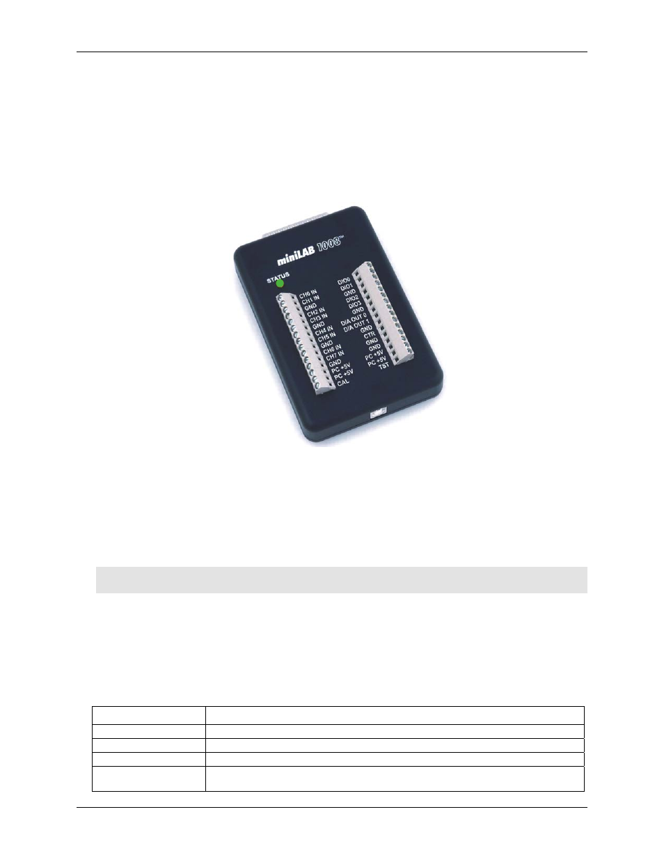
External components
The miniLAB 1008 has the following external components, as shown in
Figure 3-1. miniLAB 1008 external components
!
USB connector
!
Status LED
!
Digital I/O connector
!
Screw terminal banks (2)
USB
connector
Status LED
Screw terminal
pins 1 to 15
Screw terminal
pins 16 to 30
Digital I/O
connector
USB connector
The USB connector is located on the bottom edge of the miniLAB 1008. This connector provides +5 V power
and communication. The voltage supplied through the USB connector is system-dependent, and may be less
than 5 V. No external power supply is required.
Caution! The
USB +5V Out
pins on the DB37 connector are outputs. Do not connect an external 5 V supply
or you may damage the miniLAB 1008 and possibly the computer.
Status LED
The
STATUS
LED on the front of the miniLAB 1008 indicates the communication status. It uses up to
5 milliamperes (mA) of current and cannot be disabled.
explains the function of the miniLAB 1008
LED.
Table 3-1. LED Illumination
When the LED is…
It indicates…
Steady
The miniLAB 1008 is connected to a computer or external USB hub.
Blinks continuously
Data is being transferred.
Blinks three times
Initial communication is established between the miniLAB 1008 and the computer.
Blinks at a slow rate
The analog input is configured for external trigger. The LED stops blinking and illuminates
steady green when the trigger is received.
3-2