Main connectors and pin outs, Channel differential mode pin out, Channel single-ended mode pin out – Measurement Computing miniLAB-1008 User Manual
Page 17: Analog input terminals (ch0 in - ch7 in), Main connectors and pin outs -5, Analog input terminals (ch0 in - ch7 in) -5, Through
miniLAB 1008 User's Guide
Functional
Details
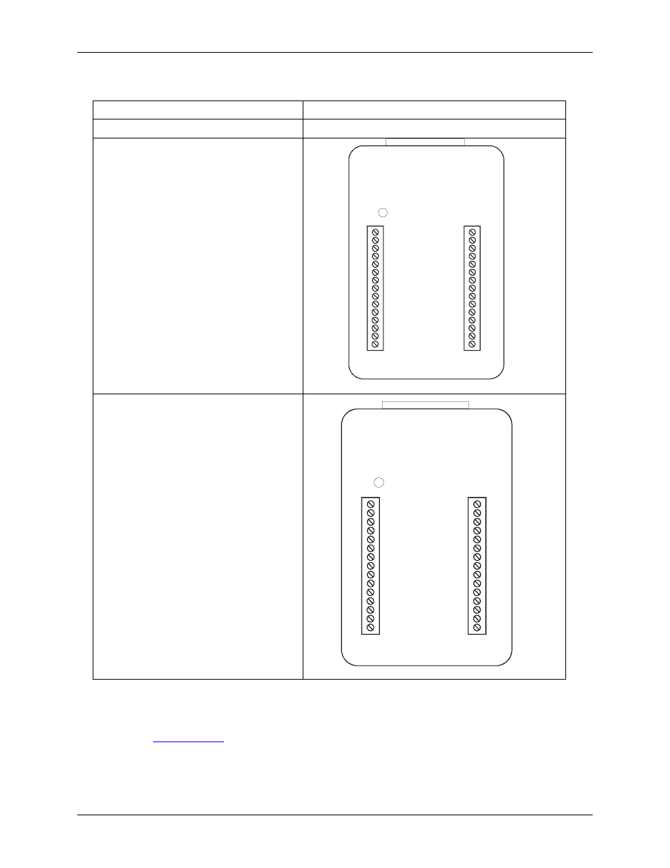
Main connectors and pin outs
Connector type
Screw terminal
Wire gauge range
16 AWG to 26 AWG
4-channel differential mode pin out
Note that the pins are labeled for 8-channel
single-ended mode on the miniLAB 1008.
CH0 IN HI
1
CH0 IN LO
2
GND
3
CH1 IN HI
4
CH1 IN LO
5
GND
6
CH2 IN HI
7
CH2 IN LO
8
GND
9
CH3 IN HI
10
CH3 IN LO
11
GND
12
PC +5 V
13
PC +5 V
14
CAL
15
16
DIO0
17
DIO1
18
GND
19
DIO2
20
DIO3
21
GND
22
D/A OUT0
23
D/A OUT1
24
GND
25
CTR
26
GND
27
GND
28
PC +5 V
29
PC +5 V
30
TST
8-channel single-ended mode pin out
Note that the pins are labeled for 8-channel
single-ended mode on the miniLAB 1008.
CH0 IN
1
CH1 IN
2
GND
3
CH2 IN
4
CH3 IN
5
GND
6
CH4 IN
7
CH5 IN
8
GND
9
CH6 IN
10
CH7 IN
11
GND
12
PC +5 V 13
PC +5 V 14
CAL
15
16
DIO0
17
DIO1
18
GND
19
DIO2
20
DIO3
21
GND
22
D/A OUT0
23
D/A OUT1
24
GND
25
CTR
26
GND
27
GND
28
PC +5 V
29
PC +5 V
30
TST
Analog input terminals (CH0 In - CH7 In)
Connect up to eight analog input connections to the screw terminal connections labeled
CH0 In
through
CH7 In
.
Refer to the
on page 3-5 for the location of these pins.
You can configure the analog input channels as eight single-ended channels or four differential channels. When
configured for differential mode, each analog input has 12-bit resolution. When configured for single-ended
mode, each analog input has 11-bit resolution, due to restrictions imposed by the A/D converter.
3-5