Functional details, 82c55 emulation, Pull-up and pull-down resistors – Measurement Computing CIO-DUAL-AC5 User Manual
Page 13
13
Chapter 3
Functional Details
82C55 emulation
The CIO-DUAL-AC5 board emulates the 82C55 chip. The 82C55 emulation initializes all ports as inputs on
power-up and reset. A TTL input is a high impedance input. If you connect another TTL input device to the
output, it could be turned on or off every time the board is reset.
To establish a consistent TTL level at power-up, use resistors tied to either +5V (pull-up) or ground (pull-
down). There are open locations for pull-up and pull-down resistor packs on the board.
Whenever an 82C55 emulation is powered on or reset, all pins are set to high-impedance input. Based on
standard TTL functionality, these inputs will typically float high, and may have enough drive current to turn on
external devices.
Unconnected inputs typically float high, but not reliably. The direction they float is dependent on the
characteristics of the circuit and is unpredictable. Consequently, if you have output devices such as solid state
relays, they may be switched on whenever the computer is powered on or reset. To prevent unwanted switching
at power-on or reset, force all digital I/O pins to a known state by pulling all pins either high or low through a
2.2 K ohm resistor tied to either 5V or GND.
Pull-up and pull-down resistors
Whenever the CIO-DUAL-AC5 is powered on or reset, the control register is set to a known state. That state is
mode 0, all ports are inputs. When used as an output device to control other TTL input devices, the CIO-
DUAL-AC5 applies a voltage level of 0V for low and 2.5V to 5V for high.
The pull-up resistor pulls the input to a high state (+5V) when the board is in input mode, as it would be on
power-up or reset. A 2.2 K ohm resistor draws only 2 mA. A grounded 2.2 K ohm pull-down resistor pulls the
I/O line low when the board is in input mode.
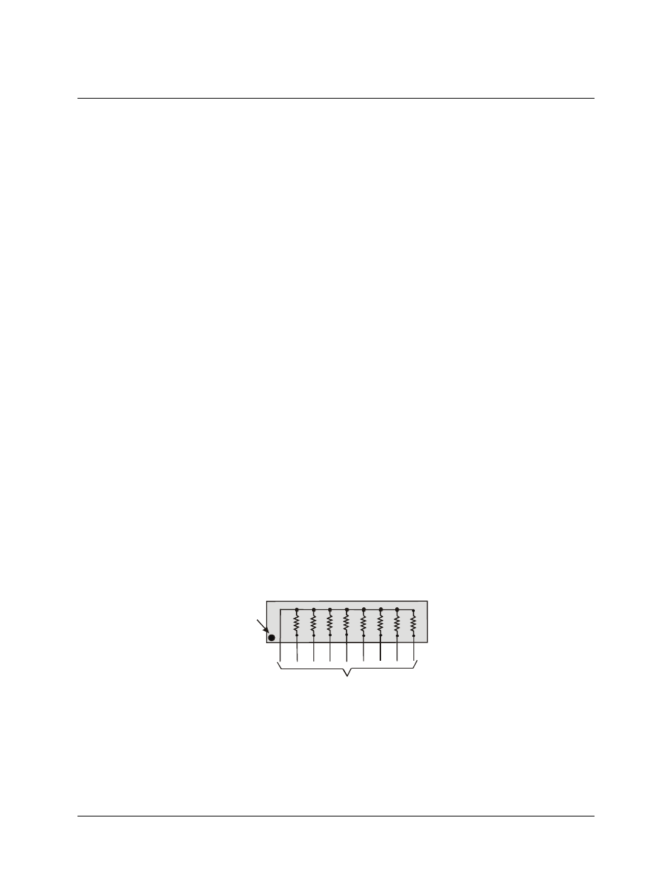
The SIP is made up of eight 2.2 K ohm resistors. One side of each resistor is connected to a single common
point and brought out to a pin. The common line is marked with a dot or line at one end of the SIP. The
remaining resistor ends are brought out to the other eight pins (refer to Figure 3).
2.2 KOhm SIP
Dot
(LO or HI)
I/O Lines
Figure 3. Eight-resistor SIP Schematic
The CIO-DUAL-AC5 board has open locations (RN1 through RN6) where you can install a 2.2 K ohm, eight-
resistor single inline package (SIP) resistor network for each port. The locations are adjacent to each I/O
connector and are marked
A
,
B
, and
C
.
Connector P1 is for the first Port A, first Port B, and first Port C I/O lines (at BASE + 0, 1, and 2). Connector
P2 is for second Port A, second Port B and second Port C (at BASE + 4, 5, and 6).