Connecting the board for i/o operations, Connectors, cables – main i/o connector, Pin out – i/o connectors – Measurement Computing CIO-DUAL-AC5 User Manual
Page 11
CIO-DUAL-AC5 User's Guide
Installing the CIO-DUAL-AC5
11
Connecting the board for I/O operations
Connectors, cables
– main I/O connector
The table below lists the board connector, applicable cables, and compatible accessory products.
Board connector, cables, and accessory equipment
Connector type
50-pin header connectors (2)
Compatible cables
C50FE-x
C50FF-x
Compatible accessory products with the
C50FE-x
SSR-PB24
Compatible accessory products with the
C50FF-x
CIO-TERM100
CIO-SPADE50
CIO-MINI50
SCB-50
SCB-100
Pin out
– I/O connectors
The CIO-DUAL-AC5 I/O uses two 50-pin header-type connectors. These connectors are board-mounted and
are not accessible on the rear of the PC expansion backplate. The signals available are direct connections to an
82C55 digital I/O integrated circuit.
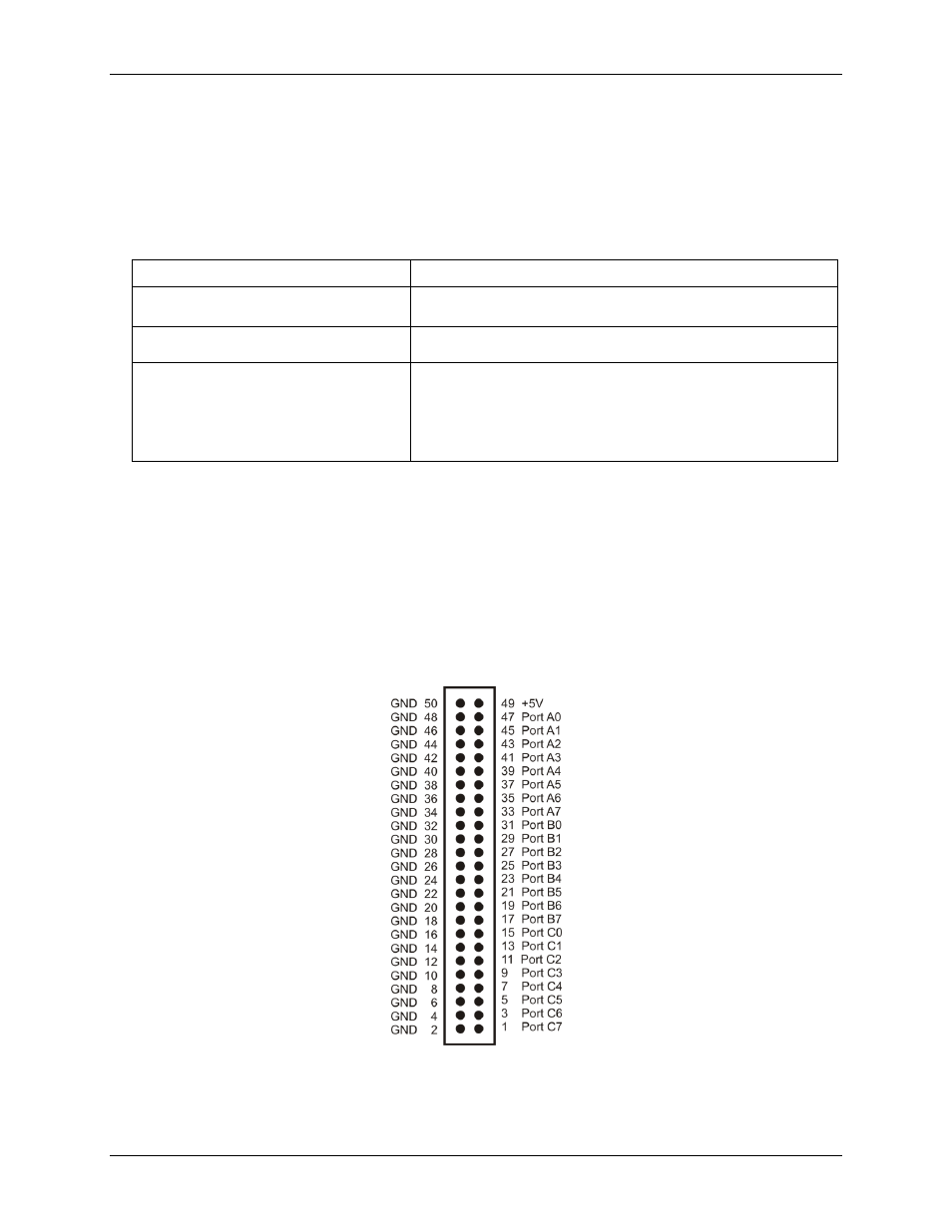
Figure 2 shows the pin outs for the connectors. The pin assignments for each are identical for each group of 24
pins (three, eight-I/O ports).
The
front
connector (P1) is for first Port A, first Port B, and first Port C I/O lines (at BASE + 0, 1, and 2).
The
rear
connector (P2) is for second Port A, second Port B and second Port C (at BASE + 4, 5, and 6).
Figure 2. I/O connector pin out
— P1 and P2 connectors