Base address – Measurement Computing CIO-DIO24/CTR3 User Manual
Page 9
CIO-DIO24/CTR3 User's Guide
Installing the CIO-DIO24/CTR3
The CIO-DIO24/CTR3 is shipped with the factory-default settings listed in the table below.
Factory-configured default settings
Switch/jumper Description
Default
setting
Base address DIP switches
Sets the base address
300h (768 decimal)
Interrupt level jumper
Sets the interrupt level
"X" position (no interrupt level set)
Wait state jumper
Enables/disables the on-board wait-state
generator.
Off (disabled)
Clock source jumpers
Sets the input signal for each counter
Not set
Review the following information to change the default configuration of a switch or jumper.
Base address
The easiest way to set the base address is to let InstaCal show you the correct settings. However, if you are
already familiar with setting ISA base addresses, you may use the base address switch description below to
guide your base address selection.
Each I/O board uses one or more I/O address locations within your computer’s I/O address space. To avoid
interference with other installed boards, each board must use unique addresses. The base address is the board’s
starting location that software writes to when communicating with the CIO-DIO24/CTR3. A set of DIP
switches is used to set the base address. By placing the switch down, the CIO-DIO24/CTR3 address decode
logic is instructed to respond to that address bit. A complete address is constructed by calculating the HEX or
decimal number which corresponds to all the address bits the board has been instructed to respond to.
The board is shipped with the base address set to 300 hex (see
. Unless there is already a board in your
system that uses address 300 hex (768 decimal), leave the switches as they were set at the factory.
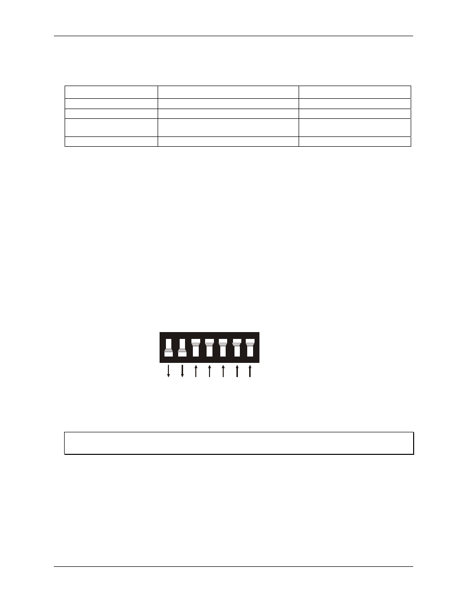
Figure 2. Base address switch
SW
A9
A8
A7
A6
A5
A4
A3
HEX
200
100
80
40
20
10
08
9
8
7
6
5
4
3
In the default configuration, addresses 9 and 8 are down, and all others are up. Address 9
= 200 hex
(512 decimal), and address 8 = 100 hex (256 decimal). When added together they equal 300 hex (768 decimal).
Disregard the numbers printed on the switch
When setting the base address, refer to the numbers printed in white on the printed circuit board.
Certain addresses are used by the computer. Other addresses are free, and may be used by the CIO-
DIO24/CTR3. Refer to the following table for a list of I/O addresses.
9