Wait state, Clock source – Measurement Computing CIO-DIO24/CTR3 User Manual
Page 11
CIO-DIO24/CTR3 User's Guide
Installing the CIO-DIO24/CTR3
Hardware interrupt assignments
Name Description
Name Description
NMI
Parity
IRQ8
Real Time Clock (AT)
IRQ0
Timer
IRQ9
Re-directed to IRQ2
(AT)
IRQ1
Keyboard
IRQ10
Unassigned
IRQ2
Reserved (XT)
IRQ11
Unassigned
INT 8-15 (AT)
IRQ3
COM OR SDLC
IRQ12
Unassigned
IRQ4
COM OR SDLC
IRQ13
80287 MUNERIC CO-P
IRQ5
Hard Disk (XT)
IRQ14
Hard Disk
LPT (AT)
IRQ6
Floppy Disk
IRQ15
Not assigned
IRQ7
LPT
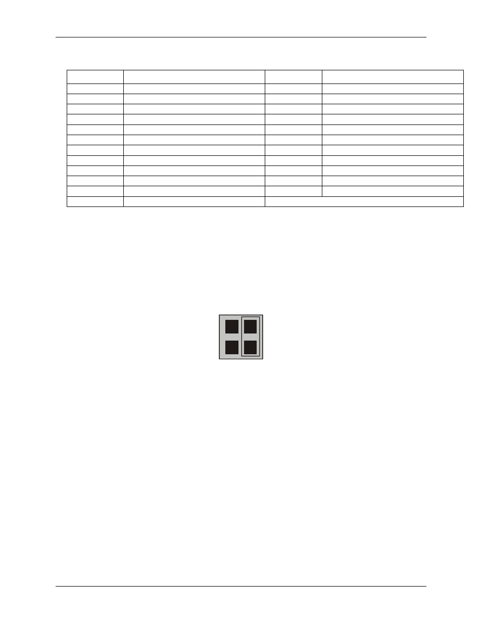
Wait state
The CIO-DIO24/CTR3 board has a wait state jumper which you can set to enable an on-board wait state
generator (see Figure 4). A wait state is an extra delay injected into the processor's clock via the bus. This delay
slows down the processor when the processor addresses the CIO-DIO24/CTR3 board, so that signals from slow
devices (chips) will be accepted. The wait state generator is only active when the CIO-DIO24/CTR3 is being
accessed. Your PC will not be slowed down in general by using the wait state.
O
N
O
F
F
WAIT
STATE
Figure 4. Wait state jumper
is configured for
OFF
(wait state is disabled).
Because all PC expansion board busses are slowed to either 8 MHz or 10 MHz, the wait state will generally not
be required. If you experience sporadic errors from the 82C55 digital I/O chip (reset, port direction swaps), try
enabling the wait state generator.
Clock source
The CIO-DIO24/CTR3 board has a bank of jumpers (
J2
) that you use to configure the clock source for the
counter 0 input (CLK 0), and also to chain the counter signals together (see
You can clock the counter 0 input to be from the board's internal 10 MHz crystal oscillator or from an external
source.
11