Installing the cio-dio24/ctr3, Figure 5 – Measurement Computing CIO-DIO24/CTR3 User Manual
Page 12
CIO-DIO24/CTR3 User's Guide
Installing the CIO-DIO24/CTR3
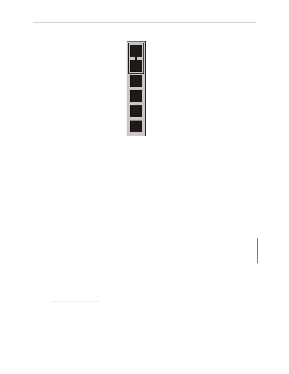
OSC
J2
CLK0
OUT0
CLK1
OUT1
CLK2
Figure 5. Clock source jumpers
Jumper the
OSC
and
CLK0
pins together to connect an internal 10 MHz crystal oscillator signal to the
counter 0 input signal.
Jumper the
OUT0
and
CLK1
pins to connect the output of counter 0 to the input of counter 1.
Jumper the
OUT1
and
CLK2
pins to connect the output of counter 1 to the input of counter 2.
You can also connect the counters externally using the signals on the 37-pin connector. However, if you chain
the counters using the connector you must provide an external source for Counter 0.
Since each counter channel is 16-bits, chaining two counters together forms a 32-bit counter. Chaining all three
counters together forms a 48-bit counter.
Installing the CIO-DIO24/CTR3
After you configure the base address, you can install the CIO-DIO24/CTR3 into your computer. Follow the
steps below.
Install the MCC DAQ software before you install your board
The driver needed to run your board is installed with the MCC DAQ software. Therefore, you need to install
the MCC DAQ software before you install your board. Refer to the Quick Start Guide for instructions on
installing the software.
1.
2.
3.
Turn your computer off, open it up, and insert your board into an available ISA slot.
Close your computer and turn it on.
To test your installation and configure your board, run the InstaCal utility you installed in the previous
section. Refer to the Quick Start Guide that came with your board
for information on how to initially set up and load InstaCal.
12