Specifications, Digital input / output, Counters – Measurement Computing CIO-DIO24/CTR3 User Manual
Page 18: Chapter 5
Chapter 5
Specifications
Typical for 25 °C unless otherwise specified.
Specifications in italic text are guaranteed by design.
Digital Input / Output
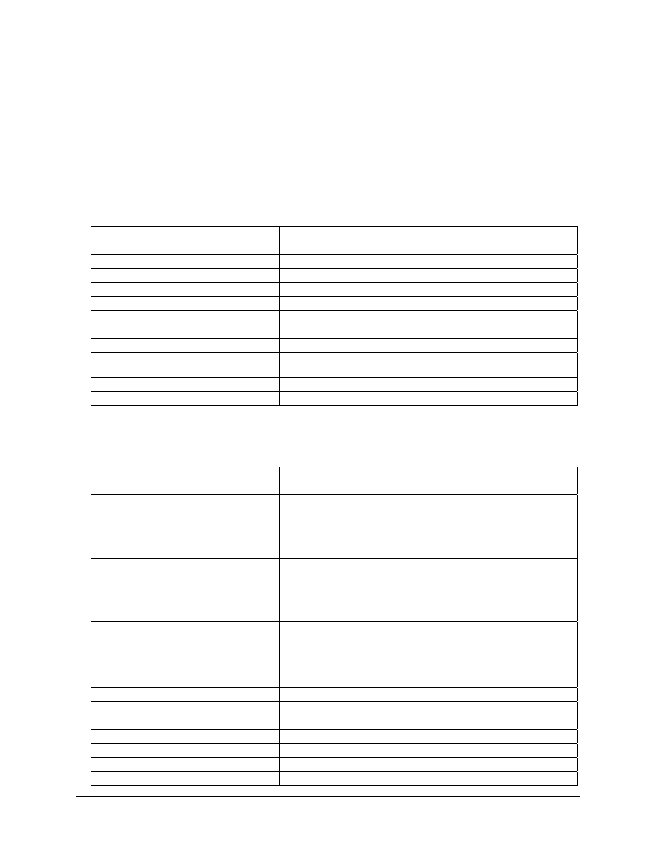
Table 1. Digital input/output specifications
Digital type
82C55
Configuration
2 banks of 8, 2 banks of 4, programmable by bank as input or output
Number of channels
24 I/O
Output high
3.0 volts min @ -2.5 mA
Output low
0.4 volts max @ 2.5 mA
Input high
2.0 volts min, 5.5 volts absolute max
Input low
0.8 volts max, -0.5 volts absolute min
Power-up / reset state
Input mode (high impedance)
Interrupts
2 through 7, jumper selectable
Interrupt enable
External (IR Enable), logic low enabled (disabled by default via internal
10k resistor to +5V)
Interrupt sources
External (IR Input), rising edge
Miscellaneous
Locations provided for installation of pull-up or pull-down resistors.
Counters
Table 2. Power consumption specifications
Counter type
82C54
Configuration
3 down counters, 16-bits each
Counter 0 - independent, user configurable
Source:
User connector (CLK0) and optionally, 10MHz
on-board xtal oscillator, selectable by jumper
Gate:
User connector (GATE0)
Output:
User connector (OUT0) and optionally, counter 1 clock
input, selectable by jumper
Counter 1 - independent, user configurable
Source:
User connector (CLK1) and optionally, counter 0
output, selectable by jumper
Gate:
User connector (GATE1)
Output:
User connector (OUT1) and optionally, counter 2 clock
input, selectable by jumper
Counter 2 - independent, user configurable
Source:
User connector (CLK2) and optionally, counter 1
output, selectable by jumper
Gate:
User connector (GATE2)
Output:
User connector (OUT2)
Clock input frequency
10 MHz max
High pulse width (clock input)
30 ns min
Low pulse width (clock input)
50 ns min
Gate width high
50 ns min
Gate width low
50 ns min
Input low voltage
0.8 V max
Input high voltage
2.0 V min
Output low voltage
0.4 V max
18