Unpacking the cio-dio24/ctr3, Installing the software, Configuring the cio-dio24/ctr3 – Measurement Computing CIO-DIO24/CTR3 User Manual
Page 8
CIO-DIO24/CTR3 User's Guide
Installing the CIO-DIO24/CTR3
Unpacking the CIO-DIO24/CTR3
As with any electronic device, you should take care while handling to avoid damage from static
electricity. Before removing the CIO-DIO24/CTR3 from its packaging, ground yourself using a wrist strap or
by simply touching the computer chassis or other grounded object to eliminate any stored static charge.
If any components are missing or damaged, notify Measurement Computing Corporation immediately by
phone, fax, or e-mail:
Phone: 508-946-5100 and follow the instructions for reaching Tech Support.
Fax: 508-946-9500 to the attention of Tech Support
Email:
Installing the software
Refer to the Quick Start Guide for instructions on installing the software on the Measurement Computing Data
Acquisition Software CD
. This booklet is available in PDF at
.
Configuring the CIO-DIO24/CTR3
The CIO-DIO24/CTR3 has a bank of base address-select switches, an interrupt level select jumper, a wait-state
jumper, and a bank of clock source jumpers. The InstaCal calibration and test program included with the CIO-
DIO24/CTR3 will show you how to configure the board. Run InstaCal to verify or change their settings before
installing the board in your computer.
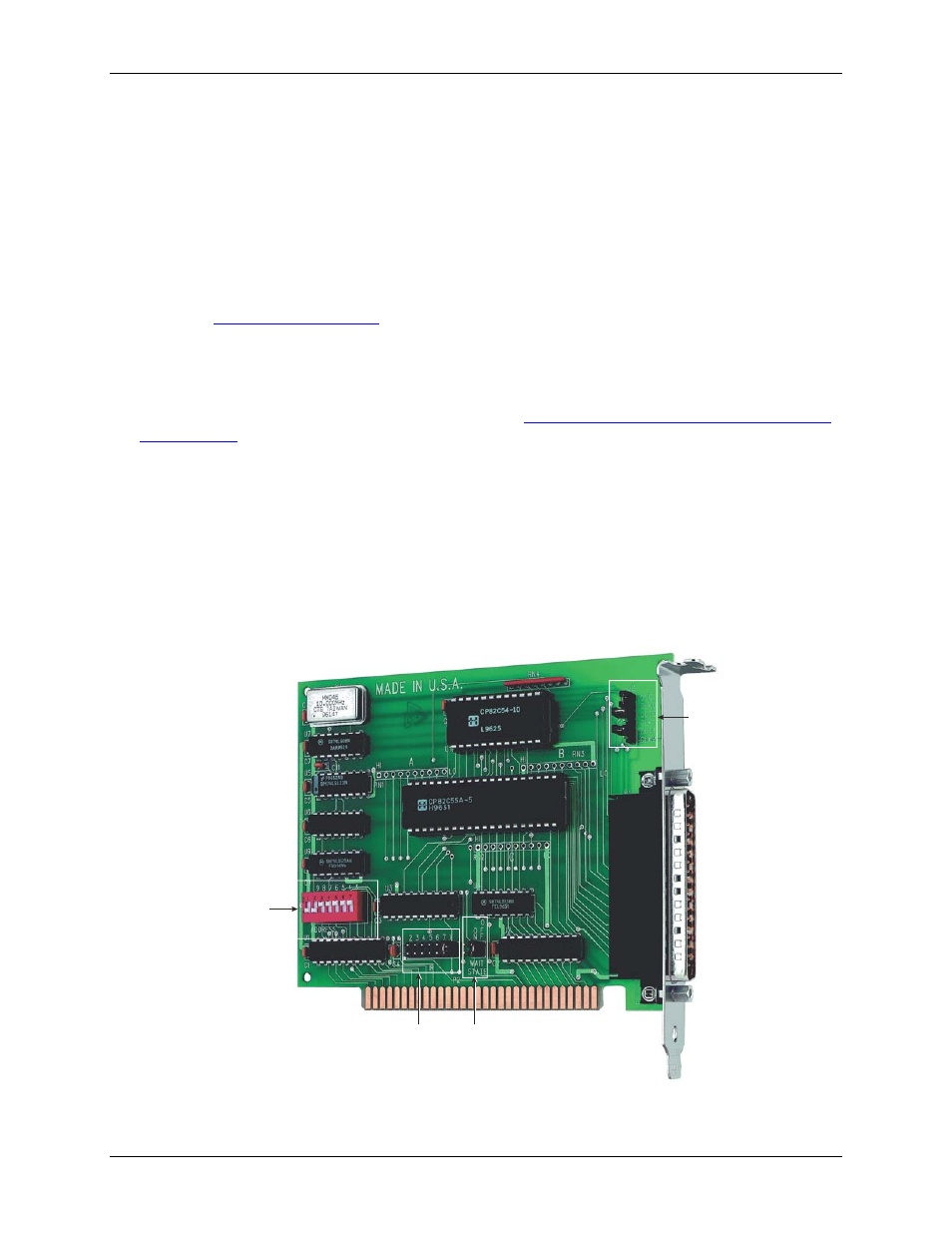
The location of each switch and jumper on the CIO-DIO24/CTR3 is shown in Figure 1.
Interrupt
Level
jumper
Base
Address
switches
Wait
State
jumper
Clock
Source
jumpers
Figure 1. Switch and jumper locations
8