Measurement Computing CIO-DAS800 User Manual
Page 8
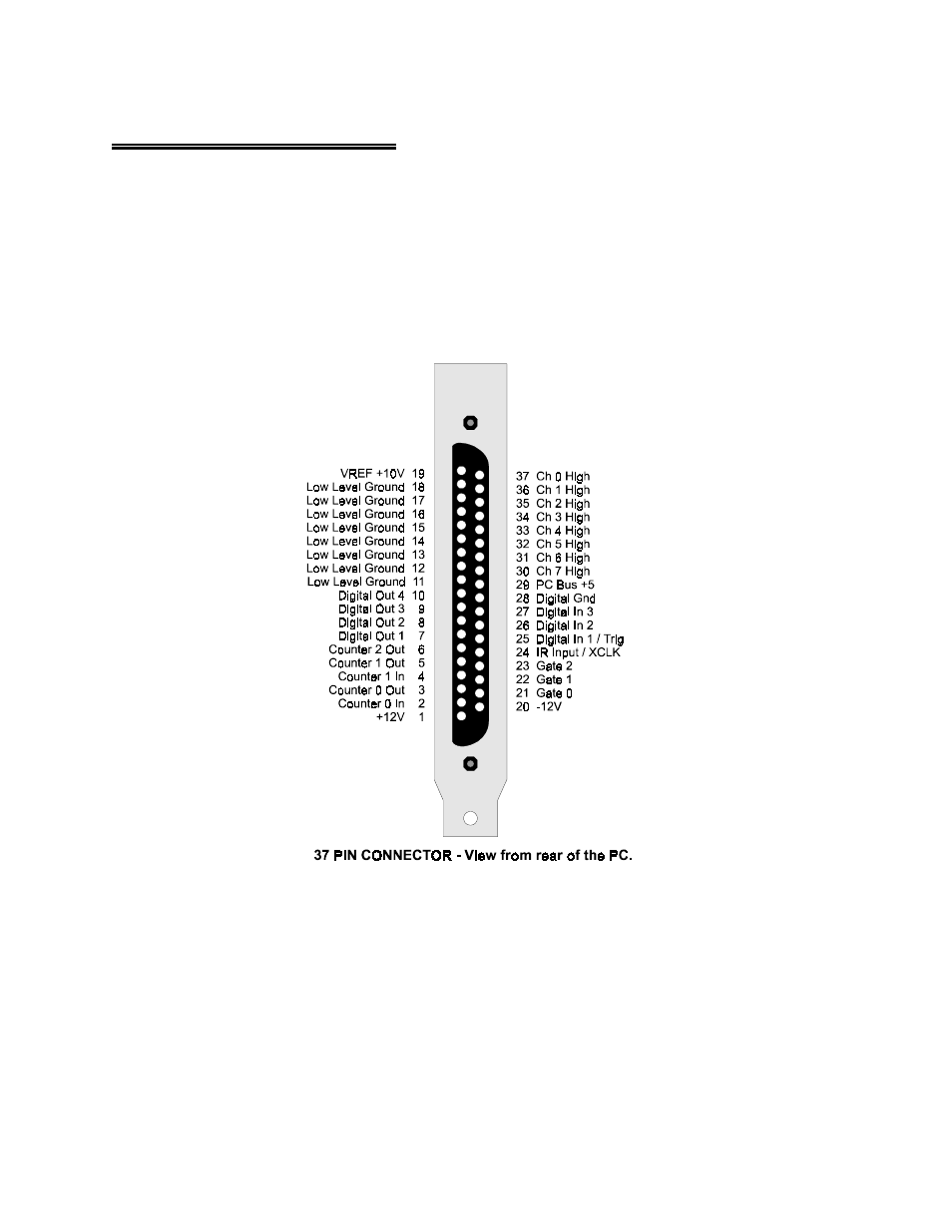
3 CONNECTOR DIAGRAM
The CIO-DAS800 analog connector is a 37-pin, D-type connector accessible from the rear of the PC
through the expansion backplate (Figure 3-1). The connector accepts female 37-pin D-type connectors,
such as those on the C37FF-2, a 2-foot cable with connectors.
If frequent changes to signal connections or signal conditioning is required, please refer to the
information on the CIO-TERMINAL and CIO-MINI37 screw terminal boards, CIO-EXP32, 32 channel
analog MUX/AMP. Isolation amplifiers can be mounted using the ISO-RACK08 and 5B isolation
modules.
Figure 3-1. Analog Connector
WARNING - PLEASE READ
Measure the voltage between the ground signal at the signal source and the PC. Use a
high input impedance voltmeter. If there more the 10 volts, do not connect the
CIO-DAS800 to this signal source because you will not be able to make a reading. If the
difference is more than 30 volts, DO NOT connect this signal to the CIO-DAS800
because IT WILL DAMAGE the board and possibly the computer.
4