2 analog output range jumpers, 3 unipolar/bipolar initial zero state jumper – Measurement Computing CIO-DAC08/16 User Manual
Page 8
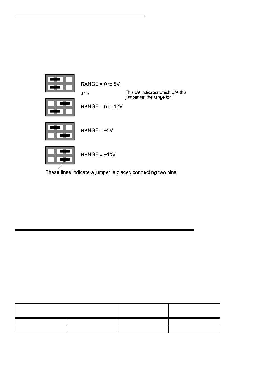
3.2 ANALOG OUTPUT RANGE JUMPERS
The analog output voltage range of each channel is set with a jumper. The jumpers
are located on the board directly below the calibration potentiometers and are labeled
J1 through J8 on the DAC08 and. J1 through J16 on the DAC16.
Set the jumpers for an individual channel as shown in Figure 3-2.
Figure 3-2. Range Jumpers
The available ranges are:
0 to 5V (Unipolar)
0 to 10V (Unipolar)
±5V (Bipolar)
±10V (Bipolar)
3.3 UNIPOLAR/BIPOLAR INITIAL ZERO STATE JUMPER
The CIO-DAC16/16 and DAC08/16 boards have a unipolar/bipolar jumper which
selects the unipolar/bipolar initial zero state of the DAC output on either power-up or
reset. There is a single jumper for the entire board (Figure 3-3). This jumper is
located near the ISA bus connector.
At power-up, the value in the DACs will be set according to Table 3-2.
Table 3-2. DAC Initial States at Power-up
0.000
Mid Scale
32768
BIP
Minus Full Scale
0.000
0
UNI
If DAC set for
Bipolar Output
IF DAC set for
Unipolar Output
DAC Code
State of UNI/BIP
Jumper
4