0 register architecture, 1 control & data registers – Measurement Computing CIO-DAC08/16 User Manual
Page 13
4.0 REGISTER ARCHITECTURE
The CIO-DAC16/16 and DAC08/16 are simple boards to understand right down to
their lowest level. All control and data is read/written with simple I/O read and write
signals. No interrupt or DMA control software is required. Thus, the board's
functions are easy to control directly from BASIC, C or PASCAL.
4.1 CONTROL & DATA REGISTERS
The CIO-DAC16/16 has 32 analog output registers, the CIO-DAC08/16 has 16.
There are two for each channel, one for the lower eight bits and one for the upper
eight bits.
The first address, or BASE ADDRESS, is determined by setting a bank of switches on
the board.
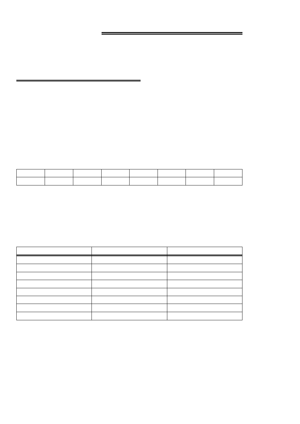
A register is easy to read and write to. The register descriptions all follow the format:
A0
A1
A2
A3
A4
A5
A6
A7
0
1
2
3
4
5
6
7
Where the numbers along the top row are the bit positions within the 8-bit byte and
the numbers and symbols in the bottom row are the functions associated with that bit.
To write to or read from a register in decimal or HEX, the bit weights in Table 4-1
apply:
Table 4-1. Bit Weights
80
128
7
40
64
6
20
32
5
10
16
4
8
8
3
4
4
2
2
2
1
1
1
0
HEX VALUE
DECIMAL VALUE
BIT POSITION
To write a control word or data to a register, the individual bits must be set to 0 or 1
then combined to form a Byte. Data read from registers must be analyzed to
determine which bits are on or off.
The method of programming required to set/read bits from bytes is beyond the scope
of this manual. Refer to a basic book on programming.
9