2 output transfer functions – Measurement Computing CIO-DAC08/16 User Manual
Page 14
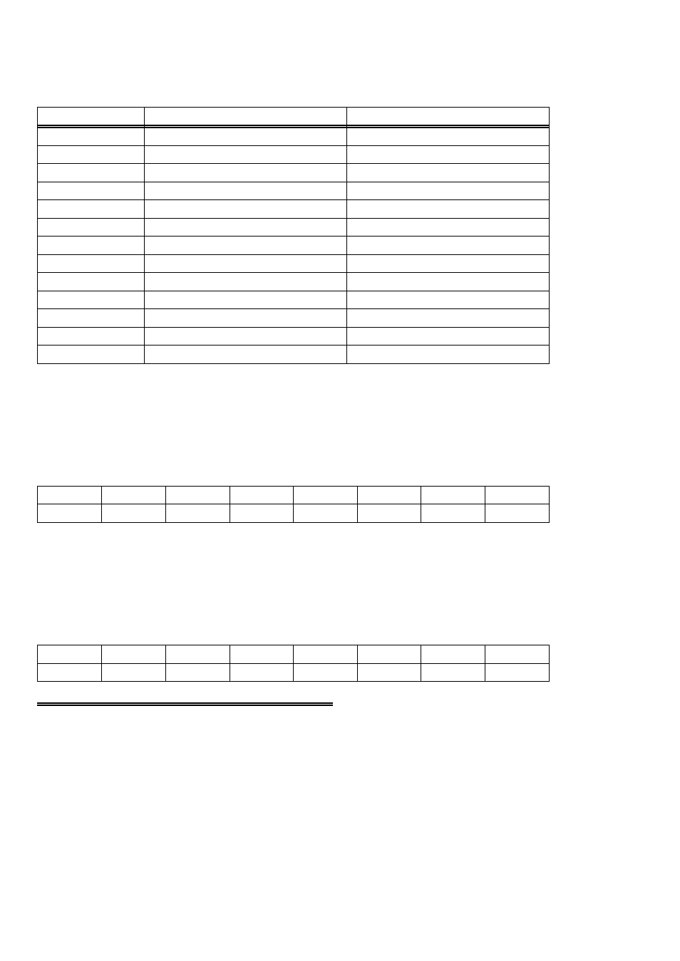
In summary form, the registers and functions are listed in Table 4-2. Each register has
eight bits which may constitute a byte of data or eight individual bit functions.
Table 4-2. Register Summary
Same.
And so on for each DAC
BASE + #
Initiate simultaneous update.
D/A 5 Most Significant Byte
BASE + 11
Initiate simultaneous update.
D/A 5 Least Significant Byte
BASE + 10
Initiate simultaneous update.
D/A 4 Most Significant Byte
BASE + 9
Initiate simultaneous update.
D/A 4 Least Significant Byte
BASE + 8
Initiate simultaneous update.
D/A 3 Most Significant Byte
BASE + 7
Initiate simultaneous update.
D/A 3 Least Significant Byte
BASE + 6
Initiate simultaneous update.
D/A 2 Most Significant Byte
BASE + 5
Initiate simultaneous update.
D/A 2 Least Significant Byte
BASE + 4
Initiate simultaneous update.
D/A 1 Most Significant Byte
BASE + 3
Initiate simultaneous update.
D/A 1 Least Significant Byte
BASE + 2
Initiate simultaneous update.
D/A 0 Most Significant Byte
BASE + 1
Initiate simultaneous update.
D/A 0 Least Significant Byte
BASE + 0
READ FUNCTION
WRITE FUNCTION
ADDRESS
The DAC16 contains 32 registers (16 register pairs). The DAC08 contains 16
registers. Each register pair controls 1 D/A output.
Each DAC has two 8-bit registers which are used to control it. The first register
contains the least significant eight bits of D/A code and should be written first.
LSB
D14
D13
D12
D11
D10
D9
D8
0
1
2
3
4
5
6
7
The second register contains the most significant eight bits of D/A code and should be
written to last. A write to this register will update the output of the D/A with all 16
bits of the D/A code contained in the two registers. If the simultaneous update jumper
is set for XFER, no update will occur until a read of any one of the DAC registers is
executed. Upon a read, all DACs will update together.
D7
D6
D5
D4
D3
D2
D1
MSB
0
1
2
3
4
5
6
7
4.2 OUTPUT TRANSFER FUNCTIONS
To program a DAC, you must select the output you desire in volts, then apply a
transfer function to that value. The transfer function for code = output is:
The UNIPOLAR transfer function of the DAC is:
10