System description – MEGA Corp. MHT175-CAT777-OPS-1 User Manual
Page 13
MHT175-CAT777(G)-1
1 Aug 2012
SECTION 2
System Description
2-5
Brake Valve & Slack Adjuster Groups
The MHT is configured with two different
brake valve and slack adjuster groups. One is
mounted in the trailer rear axle and the other is
on the tractor chassis on the rear frame.
The trailer brake valve will route activation
pressure to the trailer slack adjuster to apply
trailer brakes. The activation should occur first
in the sequencing of the three axles (trailer,
tractor drive and tractor steering). This built in
delay ensures the trailer stays in trail during
initial brake applications.
The tractor drive axle brake valve will route
activation pressure to the chassis drive axle
slack adjusters to apply drive axle brakes. This
activation will be slowed down by restrictors
in the drive axle brake valve circuit. This
delay will allow drive axle activation to occur
second in the braking sequence.
Finally, the steering tire slack adjuster will
receive activation pressure at a further reduced
rate because of smaller restrictors feeding the
steering wheel slack adjuster. This delay will
ensure steering wheel activation occurs last in
the braking sequence.
Secondary Brake System
The tractor and MHT secondary braking are
activated by pressing on the secondary brake
control pedal. This action opens the brake
retract circuit allowing the spring activated
Parking Brake System
The tractor and MHT parking brake are
activated by moving the gear selector lever to
the park position P. This action opens the
brake retract circuit allowing the spring
activated parking brake to be applied.
Brake Cooling System
The MHT axles receive brake cooling oil from
the tractor torque converter through the oil
cooler circuit. Oil is returned to the tractor
cooling circuit through the added scavenge
pump.
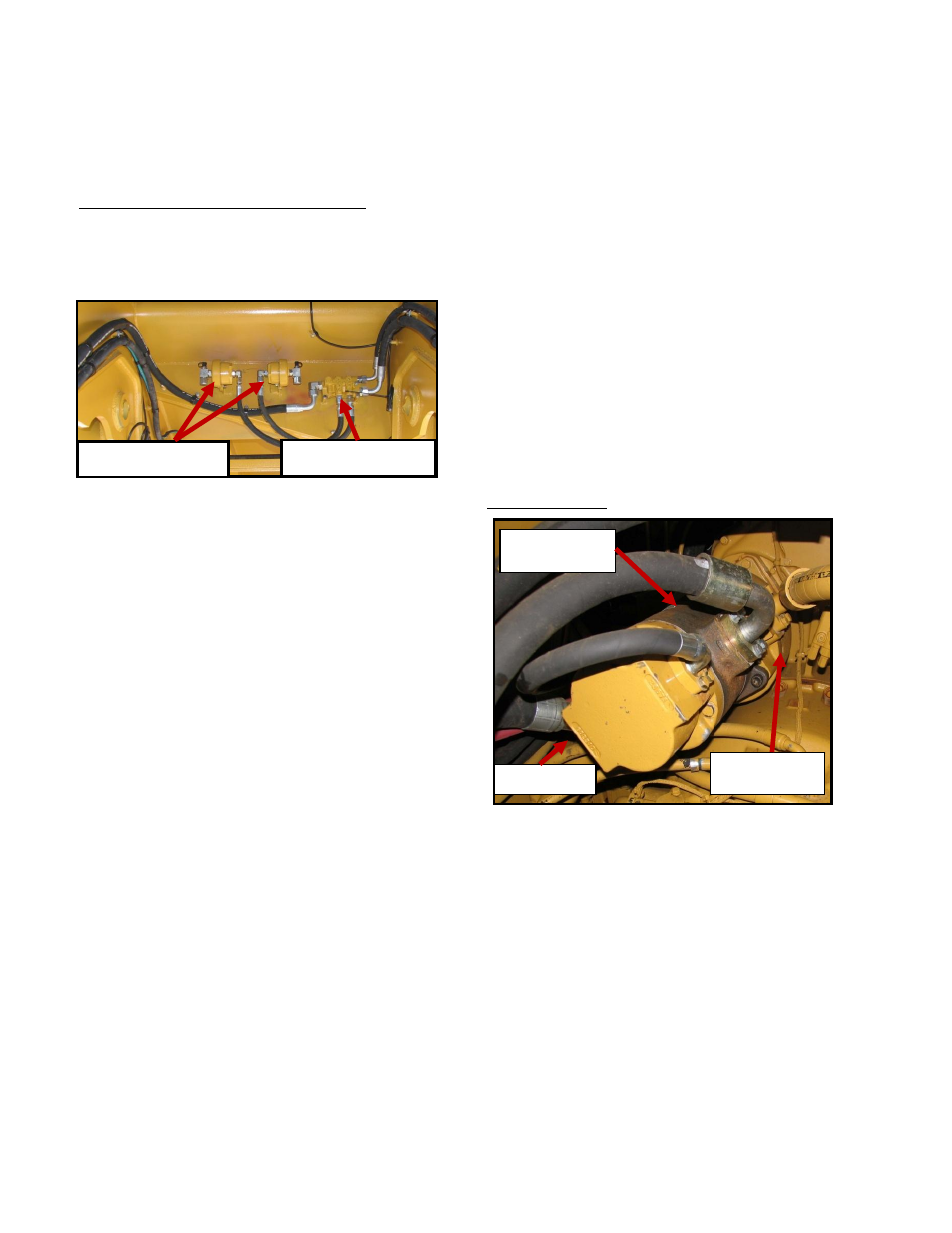
Scavenge Pump
An additional scavenge pump was added to
assist in pulling MHT brake cooling oil back
into the tractor cooling circuit. This scavenge
pump is mounted between the tractor brake
cooling pump and the brake pump. Several
restrictors were added on the steering tire
cooling circuit to allow proper oil return flow
from the trailer. Otherwise the tractor drive
axle cooling circuit is unchanged and operates
per the CAT service/operators manual.
Hoist/Brake
Cooling Pump
Added
Scavenge Pump
Brake Pump
Tractor Brake Valve
Slack Adjusters