System description – MEGA Corp. MHT175-CAT777-OPS-1 User Manual
Page 11
MHT175-CAT777(G)-1
1 Aug 2012
SECTION 2
System Description
2-3
MHT AXLE & WHEEL GROUP
The MHT trailer axle and wheel group is the
same as the tractor drive axle assembly minus
drive gear. It is attached to the MHT trailing
axle frame by means of the same A-frame,
hard pan rod and struts. For more information
see the CAT operators/service manual and
brake system information contained in this
manual.
HITCH DECK AND FENDER
The hitch deck and fender is modular in design
and is comprised of three sub assemblies. The
assemblies are the hitch and saddles, deck and
fenders.
Hitch and Saddles
Constructed of steel plates and machined brass
bushings. The assembly is mounted to the
tractor chassis and pinned to the chassis pivot
bores. The machined brass bushings capture
the MHT hitch ball and transfer loads to the
tractor. Mounting is also provided for deck
and fender assemblies.
Deck and Fenders
Constructed of square steel tubes, plates,
channels and grates that mounts to the hitch
and saddle assembly. The assembly contains
fenders, mud flaps, maintenance access doors,
walkway and a work platform.
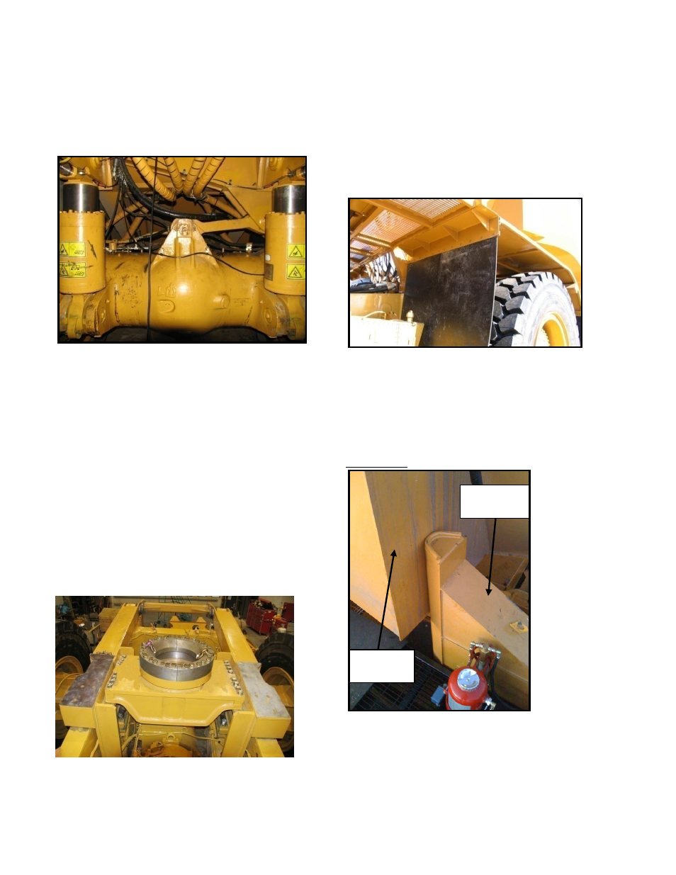
Turn Limit Indicator
Mechanical
Constructed of steel plate and mounted to the
tractor chassis rails and upper deck horse
collar. The turn limit indicator is designed to
contact the gooseneck stops and provide
visible indication of the maximum trailer
rotation left or right.
Gooseneck
Stop
Turn Limit
Indicator