Rs-485 communication, How to mount & din rail size – Delta Electronics Temperature Controller DTE User Manual
Page 2
4. This function will consume 3 ~ 5 seconds more when you switch on DTE.
RS-485 Communication
1. DTE supports baud rates 2,400/4,800/9,600/19,200/38,400/57,600/115,200 bps and does not support communication
format 7, N, 1/8, E, 2/8, O, 2. Communication protocol = Modbus ASCII or RTU.
2. Function codes: H03 = read maximum 8 words in the register; H06 = write 1 word into the register.
3. Address and contents: Every parameter has 2 communication addresses. One is numbered by the function of the
parameter, and the other is by the order of channel (as shown in the table below).
INA
INB
Content
Explanation
CH1
CH2
CH3
CH4
CH5
CH6
CH7
CH8
Present
temperature
value/input error
code
Unit; 0.1
See Table 5
H1000
(H1100)
H1001
(H1200)
H1002
(H1300)
H1003
(H1400)
H1004
(H1500)
H1005
(H1600)
H1006
(H1700)
H1007
(H1800)
Set temperature
value
Unit: 0.1
H1008
(H1101)
H1009
(H1201)
H100A
(H1301)
H100B
(H1401)
H100C
(H1501)
H100D
(H1601)
H100E
(H1701)
H100F
(H1801)
Max. temperature
value
Disabled when higher
than default value
H1010
(H1102)
H1011
(H1202)
H1012
(H1302)
H1013
(H1402)
H1014
(H1502)
H1015
(H1602)
H1016
(H1702)
H1017
(H1802)
Min. temperature
value
Disabled when lower
than default value
H1018
(H1103)
H1019
(H1203)
H101A
(H1303)
H101B
(H1403)
H101C
(H1503)
H101D
(H1603)
H101E
(H1703)
H101F
(H1803)
Error temperature
value
-999 ~ +999
Unit: 0.1°C
H1020
(H1104)
H1021
(H1204)
H1022
(H1304)
H1023
(H1404)
H1024
(H1504)
H1025
(H1604)
H1026
(H1704)
H1027
(H1804)
Proportional band
value (Pb)
0 ~ 9,999
Unit: 0.1
H1028
(H1105)
H1029
(H1205)
H102A
(H1305)
H102B
(H1405)
H102C
(H1505)
H102D
(H1605)
H102E
(H1705)
H102F
(H1805)
Ti value
0 ~ 9,999
H1030
(H1106)
H1031
(H1206)
H1032
(H1306)
H1033
(H1406)
H1034
(H1506)
H1035
(H1606)
H1036
(H1706)
H1037
(H1806)
Td value
0 ~ 9,999
H1038
(H1107)
H1039
(H1207)
H103A
(H1307)
H103B
(H1407)
H103C
(H1507)
H103D
(H1607)
H103E
(H1707)
H103F
(H1807)
Integration default
0.0 ~ 100.0%
Unit: 0.1%
H1040
(H1108)
H1041
(H1208)
H1042
(H1308)
H1043
(H1408)
H1044
(H1508)
H1045
(H1608)
H1046
(H1708)
H1010
(H1808)
Proportional control
offset error value,
when Ti = 0
0.0 ~ 100.0%
Unit: 0.1%
H1048
(H1109)
H1049
(H1209)
H104A
(H1309)
H104B
(H1409)
H104C
(H1509)
H104D
(H1609)
H104E
(H1709)
H104F
(H1809)
Proportional band
coefficient of output
1 and output 2
0.01 ~ 99.99
Unit: 0.01
H1050
(H110A)
H1051
(H120A)
H1052
(H130A)
H1053
(H140A)
H1054
(H150A)
H1055
(H160A)
H1056
(H170A)
H1057
(H180A)
Dead band of
control output 1 &
output 2.
-99.9 ~ 999.9
H1058
(H110B)
H1059
(H120B)
H105A
(H130B)
H105B
(H140B)
H105C
(H150B)
H105D
(H160B)
H105E
(H170B)
H105F
(H180B)
Hysteresis for
output 1
0 ~ 9,999
Unit: 0.1%
H1060
(H110C)
H1061
(H120C)
H1062
(H130C)
H1063
(H140C)
H1064
(H150C)
H1065
(H160C)
H1066
(H170C)
H1067
(H180C)
Hysteresis for
output 2
0 ~ 9,999
Unit: 0.1%
H1068
(H110D)
H1069
(H120D)
H106A
(H130D)
H106B
(H140D)
H106C
(H150D)
H106D
(H160D)
H106E
(H170D)
H106F
(H180D)
Read/write output
1 value
Unit: 0.1 %
H1070
(H110E)
H1071
(H120E)
H1072
(H130E)
H1073
(H140E)
H1074
(H150E)
H1075
(H160E)
H1076
(H170E)
H1077
(H180E)
Read/write output
2 value
Unit: 0.1 %
H1078
(H110F)
H1079
(H120F)
H107A
(H130F)
H107B
(H140F)
H107C
(H150F)
H107D
(H160F)
H107E
(H170F)
H107F
(H180F)
Upper limit for
alarm output
Alarm enabled
when temperature
exceeds upper limit
H1080
(H1110)
H1081
(1210)
H1082
(H1310)
H1083
(H1410)
H1084
(H1510)
H1085
(H1610)
H1086
(H1710)
H1087
(H1810)
Lower limit for
alarm output
Alarm enabled
when temperature
falls below lower
limit
H1088
(H1111)
H1089
(H1211)
H108A
(H1311)
H108B
(H1411)
H108C
(H1511)
H108D
(H1611)
H108E
(H1711)
H108F
(H1811)
Tuning for upper
limit of analog
output
Current (4 ~ 20mA)
or voltage output
tuning
H1090
(H1112)
H1091
(H1212)
H1092
(H1312)
H1093
(H1412)
H1094
(H1512)
H1095
(H1612)
H1096
(H1712)
H1097
(H1812)
Tuning for lower
limit of analog
output
Current (4 ~ 20mA)
or voltage output
tuning
H1098
(H1113)
H1099
(H1213)
H109A
(H1313)
H109B
(H1413)
H109C
(H1513)
H109D
(H1613)
H109E
(H1713)
H109F
(H1813)
Input sensor type
See “Input” section
H10A0
(H1114)
H10A1
(H1214)
H10A2
(H1314)
H10A3
(H1414)
H10A4
(H1514)
H10A5
(H1614)
H10A6
(H1714)
H10A7
(H1814)
Output function
for output 1
0: heating
1: cooling
2: proportional
output
H10A8
(H1115)
H10A9
(H1215)
H10AA
(H1315)
H10AB
(H1415)
H10AC
(H1515)
H10AD
(H1615)
H10AE
(H1715)
H10AF
(H1815)
Output function
for output 2
0: heating (default)
1: cooling
2: alarm
H10B0
(H1116)
H10B1
(H1216)
H10B2
(H1316)
H10B3
(H1416)
H10B4
(H1516)
H10B5
(H1616)
H10B6
(H1716)
H10B7
(H1816)
Control method
0: PID
1: ON-OFF
2: manual
3: PID
programmable
H10B8
(H1117)
H10B9
(H1217)
H10BA
(H1317)
H10BB
(H1417)
H10BC
(H1517)
H10BD
(H1617)
H10BE
(H1717)
H10BF
(H1817)
Alarm 1 output
mode
See “Alarm Output”
section
H10C0
(H1118)
H10C1
(H1218)
H10C2
(H1318)
H10C3
(H1418)
H10C4
(H1518)
H10C5
(H1618)
H10C6
(H1718)
H10C7
(H1818)
Alarm 2 output
mode
See “Alarm Output”
section
H10C4
(H1518)
H10C5
(H1618)
H10C6
(H1718)
H10C7
(H1818)
Heating/cooling
cycle for output 1
1 ~ 99 seconds
0 = 0.5 second
H10C8
(H1119)
H10C9
(H1219)
H10CA
(H1319)
H10CB
(H1419)
H10CC
(H1519)
H10CD
(H1619)
H10CE
(H1719)
H10CF
(H1819)
Heating/cooling
cycle for output 2
1 ~ 99 seconds
0 = 0.5 second
H10D0
(H111A)
H10D1
(H121A)
H10D2
(H131A)
H10D3
(H141A)
H10D4
(H151A)
H10D5
(H161A)
H10D6
(H171A)
H10D7
(H181A)
INA
INB
Content
Explanation
CH1
CH2
CH3
CH4
CH5
CH6
CH7
CH8
Run/Stop the
control
0: stop
1: executing
2: program stops
3: program pauses
H10D8
(H111B)
H10D9
(H121B)
H10DA
(H131B)
H10DB
(H141B)
H10DC
(H151B)
H10DD
(H161B)
H10DE
(H171B)
H10DF
(H181B)
Status of PID
auto-tuning
0: stop
1: executing
H10E0
(H111C)
H10E1
(H121C)
H10E2
(H131C)
H10E3
(H141C)
H10E4
(H151C)
H10E5
(H161C)
H10E6
(H171C)
H10E7
(H181C)
Positive/negative
proportional
output
0: positive
1: negative (slope)
H10E8
(H111D)
H10E9
(H121D)
H10EA
(H131D)
H10EB
(H141D)
H10EC
(H151D)
H10ED
(H161D)
H10EE
(H171D)
H10EF
(H181D)
Other statuses
Other statuses
H10F0
Temperature
unit
H10F1
Open special
function
(H1234)
H10F2
Return to
default
(H1357)
H10F3
Reserved
H10F4
Reserved
H10F5
Reserved
H10F6
Reserved
H10F7
Reserved
Communication
specifications
See Table 4
H10F8
Auto ID
setup
H10F9
Reserved
H10FA
Baud rate
H10FB
ASCII = 0
RTU = 1
H10FC
8 bits=0
7 bits=1
H10FD
2 stop=0
1 stop=1
H10FE
Parity
H10FF
Address
1 ~ 247
Communication Parameter Setting:
Content
0
1
2
3
4
5
6
Baud rate
2,400bps
4,800bps
9,600bps
19,200bps
38,400bps
57,600bps
115,200bps
Parity bit
None (N)
Even (E)
Odd (O)
Table 4
Error Codes:
The error codes can be read from address H1000 ~ H1007. When the input operation is in normal status, H1000 ~ H1007 are
for input values. When input error occurs (except for stable status and input exceeding the range), DTE will read error codes
in H8001 ~ H8002.
H1000 Error
description
H8001
EEPROM cannot be written in.
H8002
Input sensor is not connected.
H8003
Group INB is not connected.
Table 5
Analog output current tuning scale: 1μA/scale
Analog output voltage tuning scale: 1mV/scale
Returning to Default Value: Write H1234 into address H10F1 and H1357 into address H10F2. Restart DTE.
Programmable Communication Parameter Setting:
INA
INB
Content
Explanation
CH1
CH2
CH3
CH4
CH5
CH6
CH7
CH8
Read remaining time of the step
Unit: sec
H111E H121E H131E H141E H151E H161E H171E H181E
Read remaining time of the step
Unit: min
H111F
H121F H131F H141F H151F H161F H171F H181F
Read the NO. of the current
pattern
0 ~ 7
H1120
H1220
H1320
H1420
H1520
H1620 H1720 H1820
Read the NO. of the current step
0 ~ 7
H1121
H1221
H1321
H1421
H1521
H1621 H1721 H1821
NO. of start pattern
0 ~ 7
H1122
H1222
H1322
H1422
H1522
H1622 H1722 H1822
NO. of start step
0 ~ 7
H1123
H1223
H1323
H1423
H1523
H1623 H1723 H1823
Programmable Parameter Setting:
Content
Explanation
Pattern
0
Pattern
1
Pattern
2
Pattern
3
Pattern
4
Pattern
5
Pattern
6
Pattern
7
Max. number of
steps in the pattern
0 ~ 7 = N: The pattern
executes from step 0 to
N.
H2068
H2069 H206A H206B H206C H206D H206E H206F
Number of cycles of
pattern 0 ~ 7
execution
0 ~ 199: The pattern
has been executed for 1
~ 200 times
H2070
H2071
H2072
H2073
H2074
H2075 H2076 H2077
NO. of current link
pattern
0 ~ 8: 8 refers to end of
program; 0 ~ 7 refer to
the NO. of next pattern
H2078
H2079 H207A H207B H207C H207D H207E H207F
Address
Default
Content
Explanation
2000H ~ 203FH
0
Target temperatures for pattern 0 ~ 7
Pattern 0: 2000H ~ 2007H
Unit: 0.1°C
2080H ~ 20BFH
0
Execution time for pattern 0 ~ 7
Pattern 0: 2080H ~ 2087H
Time: 0 ~ 900 (Unit: 1 min)
4. Communication format: H03 = read bit data; H06 = write bit data
ASCII Mode:
Read Command
Read Response Message
Write Command
Write Response Message
Start word
’:’
Start word
’:’
Start word
’:’
Start word
’:’
Machine address 1
‘0’
Machine address 1
‘0’
Machine address 1
‘0’
Machine address 1
‘0’
Machine address 0
‘1’
Machine address 0
‘1’
Machine address 0
‘1’
Machine address 0
‘1’
Command 1
‘0’
Command 1
‘0’
Command 1
‘0’
Command 1
‘0’
Command 0
‘3’
Command 0
‘3’
Command 0
‘6’
Command 0
‘6’
Read Command
Read Response Message
Write Command
Write Response Message
‘1’
‘0’
‘1’
‘1’
‘0’
Length of response data
(byte)
‘4’
‘0’
‘0’
‘0’
‘0’
‘0’
‘0’
Read start address of
data/bit
‘0’
‘1’
Data address
‘1’
Data address
‘1’
‘0’
‘F’
‘0’
‘0’
‘0’
Data content in H1000
‘4’
‘3’
‘3’
‘0’
‘0’
‘E’
‘E’
Read length of data/bit
(word/bit)
‘2’
‘0’
Write data content
‘8’
Write data content
‘8’
LRC1 check
‘E’
‘0’
LRC1 check
‘F’
LRC1 check
‘F’
LRC0 check
‘A’
Data content in H1001
‘0’
LRC0 check
‘D’
LRC0 check
‘D’
End word 1
CR
LRC1 check
‘0’
End word 1
CR
End word 1
CR
End word 0
LF
LRC0 check
‘3’
End word 0
LF
End word 0
LF
End
word
1
CR
End
word
0
LF
LRC Check:
Sum up the contents from “machine address” to “data content”, e.g. H01 + H03 + H10 + H00 + H00 + H02 = H16. Obtain
2’scomplement H EA.
RTU Mode:
Read Command
Read Response Message
Write Command
Write Response Message
Machine address
H01
Machine address
H01
Machine address
H01
Machine address
H01
Command H03
Command H03
Command H06
Command H06
H10
H10
H10
Read start address of
data
H00
Length of response
data (byte)
H04
Write data address
H01
Write data address
H01
H00
H01
H03
H03
Read length of data
(bit/word)
H02
Data content 1
HF4
Write data content
H20
Write data content
H20
CRC low byte
HC0
H03
CRC low byte
HDD
CRC low byte
HDD
CRC high byte
HCB
Data content 2
H20
CRC high byte
HE2
CRC high byte
HE2
CRC low byte
HBB
CRC high byte
H15
CRC (Cyclical Redundancy Check) is obtained by the following steps:
unsigned int reg_crc = 0xffff;
i = 0;
while (length--)
{ reg_crc ^= RTUData[i];
i ++;
for (j = 0; j < 8; j++)
{ if (reg_crc & 0x01) reg_crc = (reg_crc >> 1) ^ 0xA001;
else reg_crc = reg_crc >> 1;
}
}
return(reg_crc);
Software for Setting up Communication on PC: Download the free software on Delta’s website.
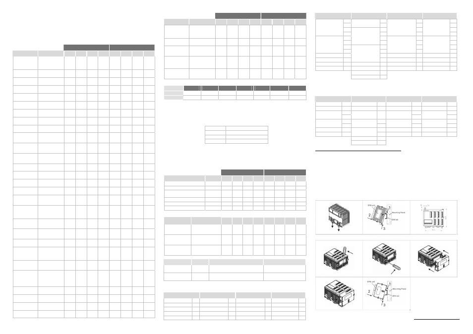
How to Mount & DIN Rail Size
Connect maximum 7 DTC2000 or DTC2001 controllers to DTE by using DIN rail.
The content of this instruction sheet may be revised without prior notice. Please consult our distributor or
download the most updated version at http://www.delta.com.tw/industrialautomation.