K-Patents DD-23 User Manual
Page 8
4
2.3.1 Overview
Red indicator
lights (alarms)
Yellow indicator
lights (warnings)
Green indicator
lights (all well)
White push-
buttons
Red push-button
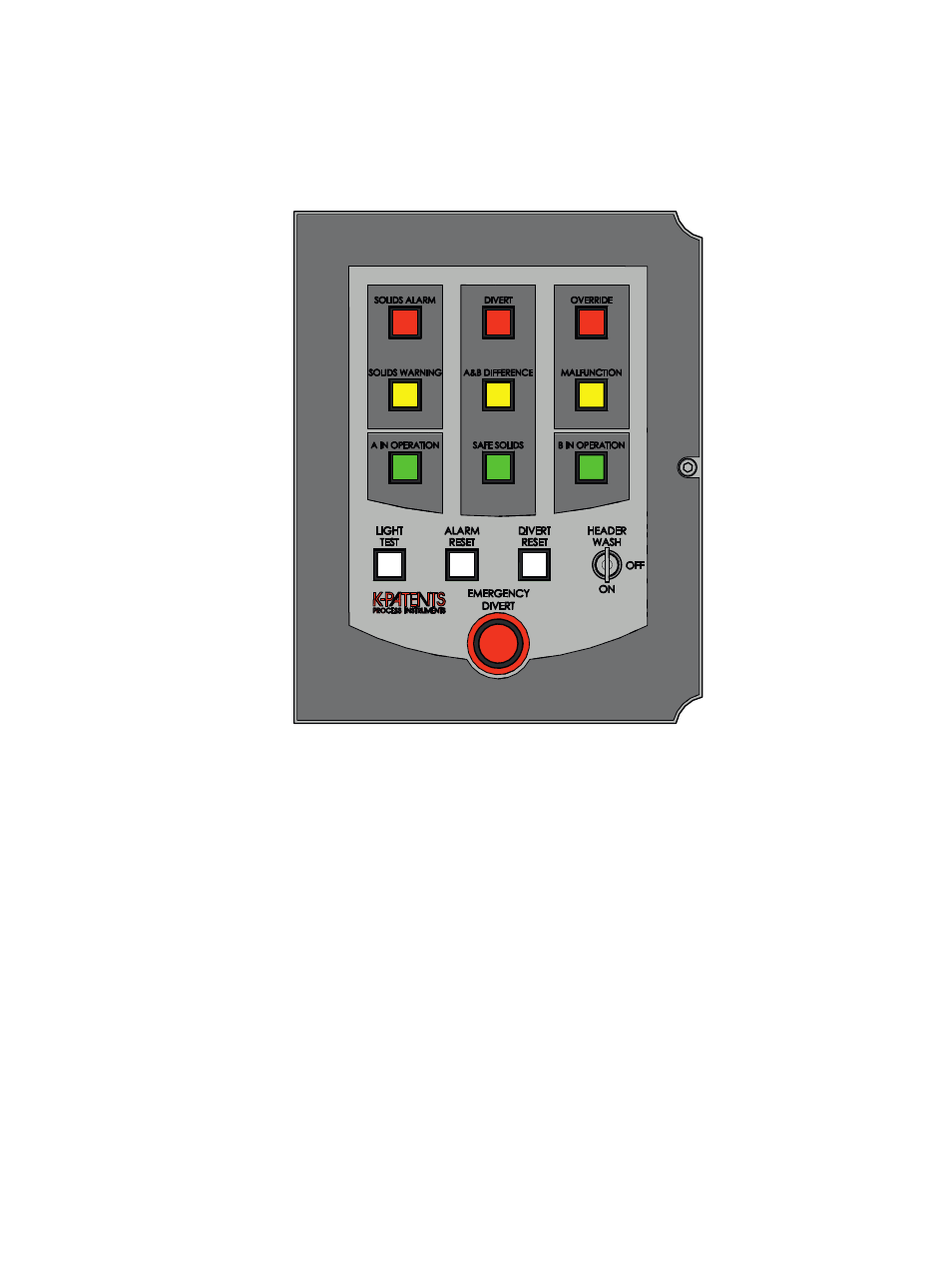
Figure 2.1
DD-23 operator panel
The three top rows on the operator panel consist of indicator lights. The green
A IN
OPERATION
and
B IN OPERATION
lights are also push buttons used to include the refrac-
tometers in the Divert system. Below the lights there are push buttons and the
HEADER
WASH
key key used to operate the system.
The indicator lights on the operator panel are arranged like trafic lights: top row is
red for alarm, middle row is yellow for warning and bottom row is green for "system
ok". When the system is running normally, only the row of green lights should be lit.
The white
LIGHT TEST
button is used to check that all the LEDs behind the indicator
lights are working. It also veriies the data processing system in the control unit. The
other two white push buttons,
ALARM RESET
and
DIVERT RESET
can be used to reset
the system back to normal after all problems have been ixed. The
HEADER WASH
key
enables the use of ring header washing with water, when set to
ON
.
The big red
EMERGENCY DIVERT
push button is used to manually initiate divert in an
emergency situation. An external push button can also be connected to a switch input
in the control unit as External Emergency divert button, see Section 2.3.8.