2 wiring – K-Patents DD-23 User Manual
Page 12
8
3.2 Wiring
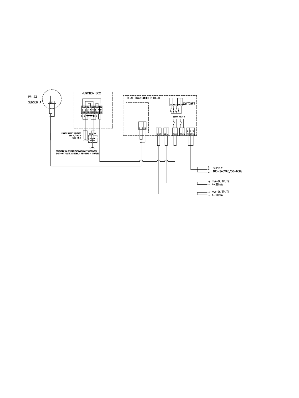
For wiring for complete system, see Figure 3.2 which shows the connections to the
Indicating transmitters and to steam washing. Figure 3.3 has information of all con-
nections to the Divert control unit.
Figure 3.2
Transmitter wiring cables and connections
3.2.1 Relays
Relay 1
NORMAL/DIVERT information
Relay 2
NORMAL/DIVERT information
Relay 3
SOLIDS WARNING: when one of the refractometers goes lower than the
solids warning limit, typically 60% or higher. See Section 5.6.1.
Relay 4
SOLIDS ALARM: when one of the refractometers goes lower than the solids
alarm limit, typically 58% or higher. See Section 5.6.2.
Relay 5
Refractometer signal difference warning: when the refractometer readings
have more than 2% difference in concentration. See Section 5.5.
Relay 6
Horn relay: connection to the audible alarm. See Section 7.5.
Relay 7
Header wash key information. See Section 3.3.3.
Relay 8
Refractometer A malfunction information. See Sections 6.2 and 7.4.
Relay 9
Refractometer B malfunction information. See Sections 6.2 and 7.4.
Relay 10
Information on if refractometer A is active in the Divert Control System or
dropped off.
Relay 11
Information on if refractomter B is active in the Divert Control System or
dropped off.