Step 1, Step 2 – Directed Electronics Nissan User Manual
Page 13
9
© 2 0 0 6 d i r e c t e d e l e c t r o n i c s
step 1
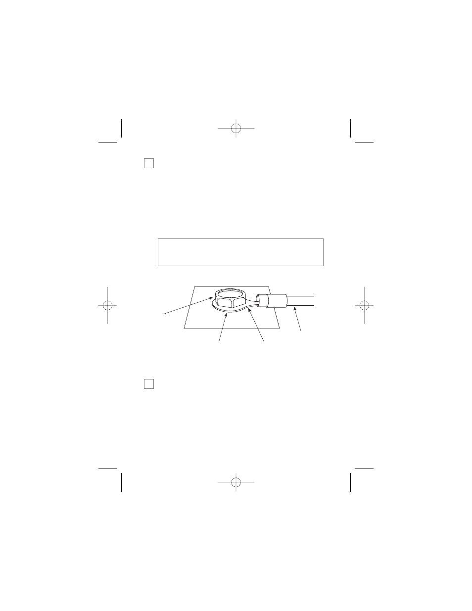
Ground Wire
The BLACK (H1/10) wire on the main 14-pin harness is ground.
This wire should be connected to a clean, paint-free area of metal
in the drivers kick panel area. Using a self-tapping screw, drill the
screw with the ring terminal to the metal area. Once screwed
down, pull on the wire to ensure a good connection.
step 2
Constant Power and Ignition wires
Almost all power and ignition wires can be found behind the key
cylinder under the lower drivers side dash panel. Using the
appropriate hand tools, remove the lower dash panel using care
not to break any parts. If the panel does not come off easily
➜
SELF-TAPPING
BOLT OR SCREW
RING
TERMINAL
GROUND
WIRE
NOTE: REMOVE ANY PAINT
BELOW RING CONNECTOR
DIA-591
note: More problems are attributed to poor ground con-
nections than any other cause. Take extra care to ensure
the ground is clean and secure.
➜
G21994_04-06.qxd 12/11/06 3:36 PM Page 9