Electrical requirements, Wiring diagram, Gas cock lubrication – Kleenmaid CH24 User Manual
Page 7
• 7 •
ELECTRICAL REQUIREMENTS:
WARNING:
✓ THIS APPLIANCE MUST BE EARTHED.
CAUTION:
✓ Ensure that the power outlet is properly earthed
before connecting the appliance.
✓ Disconnect power before servicing the appliance.
The appliance is provided with a standard 240VAC three
pin plug and power cable (3X0.75 mm
2
).
The wires in the power cable are coloured in accordance
with the following code: Green/Yellow = Earth, Blue =
Neutral, Brown = Active.
If the colours of the wires in the power cable to the
appliance do not correspond with the coloured markings
identifying the terminals in the junction terminal, proceed
as follows:
1. The wire which is coloured green and yellow must be
connected to the terminal marked E (Earth) or
coloured Green.
2. The wire which is coloured blue must be connected to
the terminal marked N (Neutral) or coloured Black.
3. The wire which is coloured brown must be connected
to the terminal marked L (Live) or A (Active) or
coloured Red.
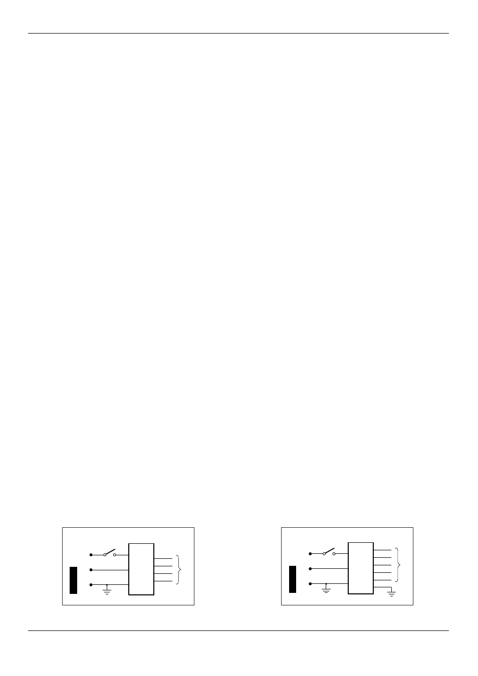
WIRING DIAGRAM:
IGNITION
MODULE
240 VAC
50 Hz
0.5 VA
DANGER
240 V
A
C
Ignition
Switch
To
Electr
odes
A
N
E
IGNITION
MODULE
240 VAC
50 Hz
0.5 VA
DANGER
240 V
A
C
Ignition
Switch
To
Electr
odes
A
N
E
CH24 - CH25 - CH26
CH84W - CH85S - CH86B
CH35 - CH95S
Figure 9
Figure 10
REPLACEMENT OF IGNITION
MODULE/ELECTRODES/GAS COCKS:
1. Turn off and disconnect gas supply and electricity.
2. Lift off trivets and burner heads, and pull off igniter
and control knobs.
3. Undo the screws “B” and remove the clamps “A”
shown in Figure 4 and remove the hob.
4. Remove screws securing the top of the hob to the
base pan and lift it off.
5. To replace the electrode, unhook the locking spring
and remove the electrode and cable.
6. To remove the igniter module, disconnect the
electrodes, power and igniter switch wires, undo the
two retaining screws and remove the module.
7. To remove the gas cock undo the two screws which
secure it to the gas manifold. On re-assembly ensure
that the injectors are aligned with the burner venturi.
8. Reassemble in reverse order
9. Check all connections for gas leaks with soapy water
(including gas cocks if they have been removed).
GAS COCK LUBRICATION:
1. Turn off gas supply and disconnect electricity.
2. Remove the knobs and ignition push button
3. Unscrew the “A” screw in Figure 6
4. Remove the control panel “B” in Figure 6
5. Unscrew the two screws on top of the gas cock
6. Lift out the valve cone, clean it with solvent and re-
grease it with high temperature grease
7. Replace the valve cone, move it around and remove
excess grease. Remove it once again and check that
internal holes or galleries are not blocked.
8. Replace and reassemble in reverse order.
9. Check for gas leaks with soapy water.