Installation, Gas supply – Kleenmaid CH24 User Manual
Page 5
• 5 •
INSTALLATION
(Refer to Figures 4 and 5):
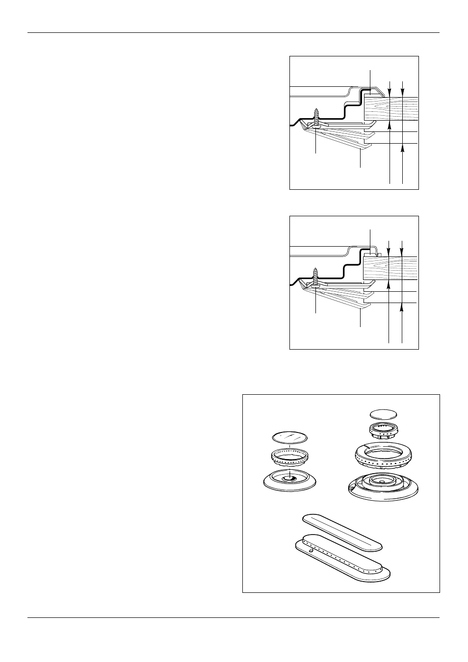
1. Spread out the gasket “C” over the workbench at the
edge of the cut out taking care to overlap the gasket
at the corners.
2. Slot in the cooking hob into the cut out of the
workbench and locate it correctly.
3. Adjust the clamps “A” and tighten the screws “B” until
the hob is firmly secured.
4. Using a sharp tool, trim any excess gasket which
protrudes from the edge of the hob.
5. Assemble the three piece burners. Take care to
properly locate the assembled burner on the burner
base.
,,,
,,,,,,,,,
,,,,,,,,,
20 mm min.
40 mm max.
B
C
A
Figure 4
,,,
,,,,,,,,,
,,,,,,,,,
20 mm min.
40 mm max.
B
C
A
GAS SUPPLY:
✓ This appliance is suitable for use with Natural Gas or
LPG. (Check the “gas type” sticker attached to the
appliance).
✓ For Natural Gas models the gas supply is connected to
the pressure regulator which is supplied with the
appliance. Adjust the regulator to obtain a test point
pressure of 1 kPa with the two largest burners
operating.
✓ For LPG models connect the gas supply directly to the
appliance inlet connection and ensure that the supply
pressure is regulated to 2.75 kPa.
✓ Do NOT force the “elbow” rotation prior to
loosening the nut.
✓ Do NOT over tighten the nut at the “elbow”.
1. After connecting the gas supply, check the piping and
connections for leaks using a soap and water solution.
The presence of bubbles indicates a leak, tighten or
replace connections as appropriate.
2. Adjust the test point pressure or supply pressure to
the value which is appropriate for the gas type.
3. Turn on the appliance gas controls and light each
burner. Check for a well defined blue flame without
any yellow tipping. If any abnormality is evident then
check that the burner cap is located properly and the
injector nipple is aligned correctly.
4. Check the minimum burner setting by quickly rotating
the gas control knob from the maximum to the
minimum position, the flame must not go out. If
adjustment is required carry out the “minimum burner
setting adjustment" procedure described below.
5. If satisfacfory performance cannot be obtained isolate
the appliance and contact the local gas authority for
advice and assistance.
Figure 5