Hypertherm MAX200 Service Manual User Manual
Page 60
MAX200
Service Manual
3-19
1-97
MAINTENANCE
• Verify that the torch cap is on tight, and that no hissing
from gas leakage is heard.
• Check for damage to O-rings in the torch main body. See
Figure 3-3 for location of torch main body and O-rings for
hand torch, and Figure 3-6 for machine torch.
3d.2. Pressure switch PS2 not functioning.
PS2 is normally open, and closes when shield gas
pressure is 70 psi or greater. After PS2 is closed, the
SHIELD GAS/CAP LEDextinguishes.
• Using the 013-2-179 wiring diagram, check pins,
connectors and associated wiring from REC3 on the
Power Distribution Board to PS2.
3d.3. Solenoid valve V4 not functioning.
V4 is normally closed and opens when 24VAC is applied.
See Figure 4-6 for location of V4.
• Using the 013-2-179 wiring diagram, check pins,
connectors and associated wiring from REC3 on the
Power Distribution Board to V4.
Repair and/or replace defective component(s) if necessary.
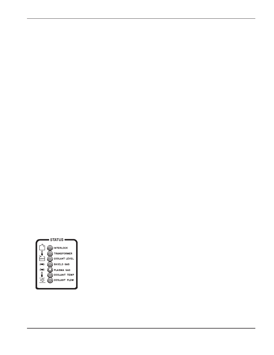
3e. PLASMA GAS LED
illuminated:
3e.1. Plasma gas pressure too low.
This LED will extinguish when PS1 senses plasma gas
pressure of 60 psi or greater. Refer to Figure 4-4 for
location of PS1, and Figure 3-14 for gas interconnect
diagram.
• Verify that plasma gas supply is set to specifications in
Cut Chart Tables in Section 4 of MAX200 Instruction
Manual (#800870 or #800980).
• Verify that all Plasma Gas connections are secure, and
that there are no leaks in the hosing. See Figure 4-10 for
location of plasma gas supply bulkhead.
Problem
Possible Causes and Solutions
/CAP