Operation -8, Adjustment -8, Operation -8 adjustment -8 – Hypertherm LH2100 User Manual
Page 35
1
OPERATION
4-8
LH2125/LH2100 Laser Head Instruction Manual
Adjustment
The capacitive height sensor interface box (051008) provides digital outputs for the tip-touch, over-range, and under-
range signals. It also provides an analog signal that measures the distance from the nozzle to the material.
1. Set the gain knob to mid range (5.0).
2. Position the cutting head so the distance between the nozzle and the work piece is 10 mm.
a. If the over-range LED is illuminated, decrease the Offset knob until the LED is extinguished and then slowly
increase the knob until the LED illuminates again. Lock the knob and record the setting.
b. If the over-range LED is extinguished, increase the Offset knob setting until the LED illuminates. Lock the
knob and record the setting.
c. If the over-range LED is still illuminated when the offset knob is set to 0.0, remove the nozzle and the nozzle
adapter retaining ring. Inspect the condition of the o-ring and the ceramic layer on the nozzle adapter.
Replace if necessary. Reinstall the nozzle adapter and nozzle, tighten both appropriately. Repeat steps 1
and 2.
d. If the over-range LED is still illuminated, decrease the R2-Gain knob until the over-range LED is extinguished.
e. If both R1 and R2 knobs are set to 0.0 and the over-range LED is still illuminated the nozzle adapter may be
damaged. Replace with new a nozzle adapter and repeat steps 1 and 2.
Continued on next page
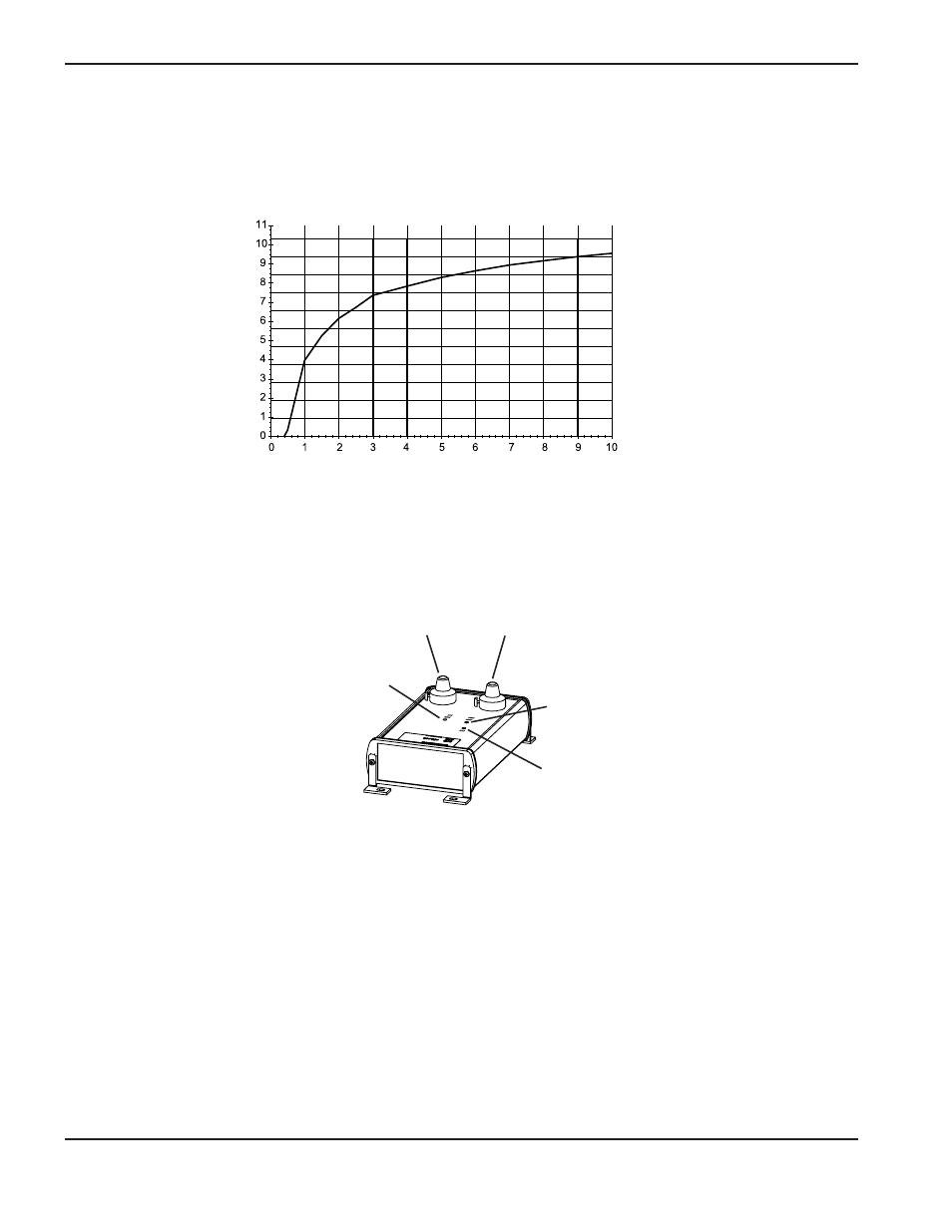
Power LED
Over range LED
Under range LED
Gain knob
Offset knob
Operation
The capacitive height sensor interface has gain and offset adjustments. It is calibrated to have a signal of 0.0V at a
nozzle-to-workpiece height between 0.3 and 0.4 mm and an over-range signal at a stand off of 10 mm. The output curve
of voltage versus distance should be similar to the graph shown below when properly adjusted.
Displacement (mm)
Signal (volts)