Single channel interface box installation -7, Controller cable connector information -7, Connect cables -7 – Hypertherm LH2100 User Manual
Page 22: Single-channel interface box installation -7, Single-channel interface box installation
single-channel interface box installation
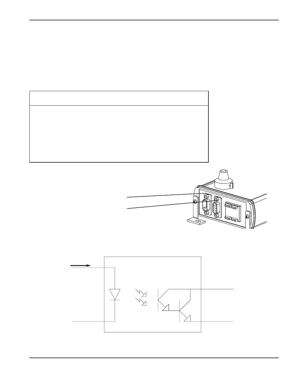
The single-channel interface box provides 3 independent optically isolated outputs. Outputs can be used by the
controller to detect piercing and cutting operations.
Controller cable connector information (9 pin D-Sub)
J1 pin-outs (Output To Controller)
Output Circuit
+ Output
+ Output
MOC8050
I
f
= 2mA
Connect cables
Controller cable – 9 pin cable to controller
Sensor cable – interface box to laser head
Pin
Wire
Number
Color
Description
1
Red
Voltage in+ (9-36 VDC, 2 watts maximum)
2
Black
Voltage in-
3
White
Cut error +
4
Green
Cut error -
5
Blue
Continuous wave pierce complete +
6
Brown
Continuous wave Pierce complete -
7
Orange
Pulsed pierce complete +
8
Yellow
Pulsed pierce complete -
9
Shield
Electromagnetic protection (earth ground)
1
INSTALLATION
LH2125/LH2100 Laser Head Instruction Manual
3-7
Note: Nominal voltage drop across output (+/-) is 1.2 volts. Current must be limited by input
resistance.