Operating controls, Extension and switch assembly, Starting and stopping saw – Delta 36-465 User Manual
Page 18: Locking switch in the “off” position, Overload protection, Assembling steel extension wing and switch
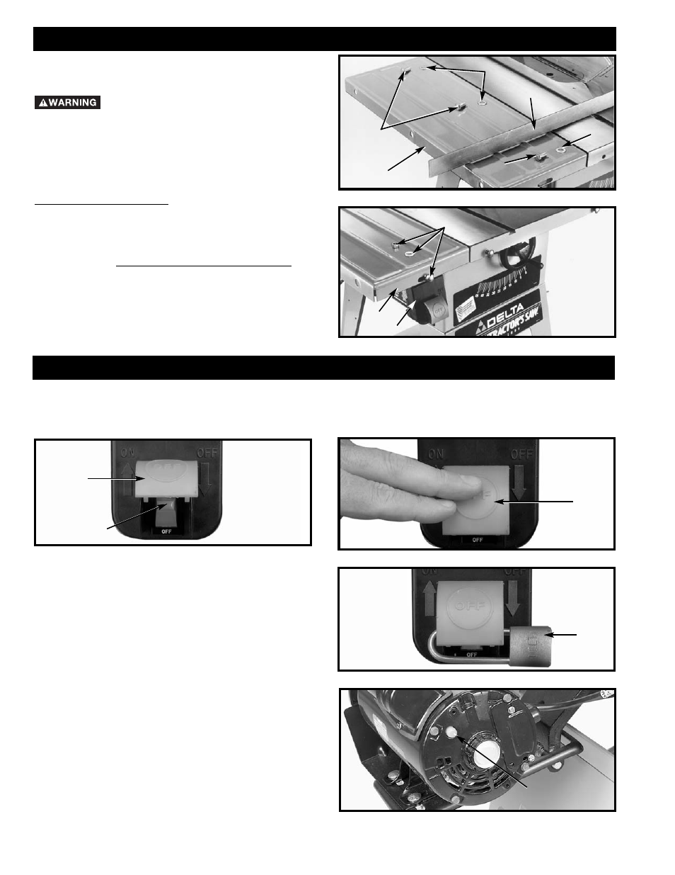
Fig. 40
A
STARTING AND STOPPING SAW
1. The on/off switch is located underneath the switch shield (A) Fig. 37. To turn the saw “ON”, move
switch trigger (B) to the up position.
2. To turn the saw “OFF”, push down on switch shield (A) Fig. 38.
Fig. 37
Fig. 38
A
B
A
Fig. 39
LOCKING SWITCH IN
THE “OFF” POSITION
IMPORTANT: When the machine is not in use, the
switch should be locked
in the “OFF” position to
prevent unauthorized use,
using a padlock (C) Fig. 39
with a 3/16" diameter shackle.
In the event of a power outage, always lock switch in
“OFF” position until the main power is restored.
OVERLOAD PROTECTION
Some saws are equipped with motors that do not have
a resettable overload. However, if your motor is
equipped with a resettable overload and the motor shuts
off or fails to start due to overloading, move the switch
to the “OFF” position and let the motor cool three to five
minutes. After cooling for three to five minutes, push the
reset button (A), Fig. 40. The saw can then be turned on
again in the usual manner. Note: Overloading occurs due
to cutting stock too fast, using a dull blade, using the
saw beyond its capacity, low voltage, and etc.
C
OPERATING CONTROLS
18
Fig. 35
ASSEMBLING STEEL EXTENSION
WING AND SWITCH
DISCONNECT MACHINE FROM POWER
SOURCE.
1.
Assemble extension wing (A) Fig. 35, to the saw table
using three 7/16-20 x 3/4" bolts (B) and flat washers (C).
2.
With a straight edge (D) Fig. 35, make certain the
extension wing (A) is level with the saw table before
tightening three bolts (B).
3.
Loosely assemble switch bracket (E) Fig. 36, to the
rear of extension wing (A) and fasten with 3/8-16 x 1" long
carriage head bolt through hole, then add flat washer,
and hex nut (S). Tighten after fence rail assembly.
C
D
C
B
B
A
Fig. 36
S
A
E
EXTENSION AND SWITCH ASSEMBLY