Herrmidifier Herrmersion RE User Manual
Page 17
Herrmersion RE
I n s t a l l a t i o n , O p e r a t i o n , & M a i n t e n a n c e M a n u a l
17
www.herrmidifier-hvac.com
or reverse osmosis water applications rarely require the
Auto DRN feature to be enabled as the water contains
very low dissolved solids.
• DRN Int – Drain Interval is the interval at which the unit
will initiate a timed drain. The default interval is factory
set at 24 hours.
• DRN Time – Drain Time is the amount of time the drain
valve will remain open if a timed drain is active. The
DRN Time is factory set at 5 minutes.
• Skim Time – Skim Time is the amount of time the unit
will continue filling to skim the surface of the water every
time a fill cycle is active. This feature may be set to zero
if the system is operating with very clean water; such as
de-ionized water. The factory Skim Time is 60 seconds.
Low water pressure may require that this setting be
increased so that the unit will skim.
• DRN Tmpr – Drain Tempering will activate the fill valve
anytime the drain valve is active. This feature acts to
lower the drain water temperature by diluting the drain
water with cold fill water. Water ensuing from the
skimmer port on the tank is not tempered. An external
drain water tempering device may be required. Please
consult the factory for information about the Drain
Tempering Reservoir, available separately.
• Force DRN – Force Drain is used to manually initiate a
drain cycle. The drain valve will remain active until this
parameter is set to OFF by the operator.
• RETURN – Returns the operator to the Home screen.
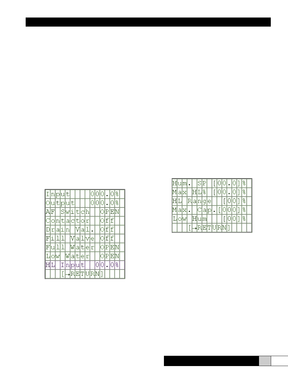
Status Menu
The Status menu contains a list of system inputs/outputs that
may be monitored by the operator.
• Input – This displays the percentage of demand when the
unit is configured for Proportional only operation. The
demand signal is received from a building management
system or from a remote humidity controller. This
displays the controlled relative humidity percentage
when the unit is configured for stand-alone P+I control.
The signal is received from a humidity transmitter
mounted in the controlled environment.
• Output – This displays the percentage of maximum unit
output.
• AF Switch – This displays whether the air proving switch
is OPEN or MADE. OPEN indicates a lack of airflow.
MADE indicates that the switch contacts are closed
indicating that airflow is present.
• Contactor – This displays ON/OFF status of the main
power contactor. This is monitoring the status of the
auxiliary contact on the main power contactor.
• Drain Val. – This displays the ON/OFF status of the drain
valve output.
• Fill Valve – This displays the ON/OFF status of the fill
valve output.
• Full Water – This displays the OPEN/MADE status of
the upper water level float switch. Each time this switch
opens, the unit will act to refill the tank for continued
humidification if a demand is present.
• Low Water – Displays the OPEN/MADE status of the
lower water level float switch. This switch must be
MADE in order for the heating elements to be energized.
• HL Input – Displays the relative humidity percentage
being sensed by the High Limit humidity sensor.
This item will not show in the menu unless the unit is
configured for stand-alone P+I control. If the unit has a
High Limit humidistat in lieu of a transmitter, this menu
item will read High Limit and the status will read OPEN
or MADE to indicate the status of the humidistat (switch).
Setpoints Screen
The Setpoints Screen will only be visible on units that are
configured for stand-alone P+I control. The HOME screen
will display RES-I. This means that a control humidity sensor
and high limit humidity sensor need to be connected to inputs
1 & 2 of the control board. Please see the wiring diagram
appropriate for the unit model being installed.
• Hum. SP – The user may enter the control humidity
setpoint here. Default = 40%RH.
• Max HL% – The operator may enter the maximum
allowable duct high limit %RH here. Default = 80%RH
• HL Range – The High Limit range sets the percentage
offset where the unit will begin to throttle the unit output
proportionally between the Max. HL% minus the HL
Range. Example: If the Max. HL% is set to 80% and
the HL Range is 10%, the unit will be limited to 50% of
maximum output if the high limit duct sensor is reading
75% relative humidity in the duct.
• Max. Cap. – Maximum Capacity allows the operator to
limit the maximum unit output based on a percentage.
Example: If the unit has a maximum capacity of 90 lb/