5 electrical connections – Guralp Systems CMG-5T User Manual
Page 9
Operator's Guide
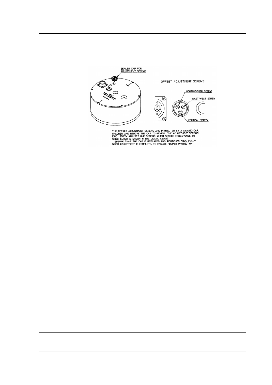
1. Remove the screwed cover protecting the level adjusters. The
cavity contains three adjustment screws, which are arranged as
shown in the diagram below:
2. Power up the sensor, and connect a digital multimeter to its
low-gain vertical outputs (pins L and M). Alternatively, use a
Güralp Systems CMG-5T hand-held control unit to monitor the
outputs more easily.
3. Adjust the vertical screw until the output voltage reads zero.
4. Repeat steps 2 and 3 for the N/S and E/W channels, (pins C/D
and K/U respectively).
5. If necessary, continue to adjust each channel in turn until
consistent results are obtained on all three channels.
6. Repeat steps 2 to 5 using the high-gain outputs, if available, and
refine the settings as far as possible.
7. Replace the protective cover firmly, to keep the instrument's
electronics protected from water and dust.
After the cover is installed, the accelerometer outputs may drift until
the system establishes temperature equilibrium with its environment
and the sensor settles down in its position. If required, the offset
adjustment can be repeated to achieve a better output offset. With
experience, it should be possible to reduce the output level to less than
± 1 mV.
2.5 Electrical connections
Each channel inside the 5T sensor has four output lines: a pair of
December 2009
9