Guralp Systems CMG-1T User Manual
Page 19
Operator’s Guide CMG-1T Ocean Bottom
Seismometer
September, 1999, Issue C Section 3,
Page 3
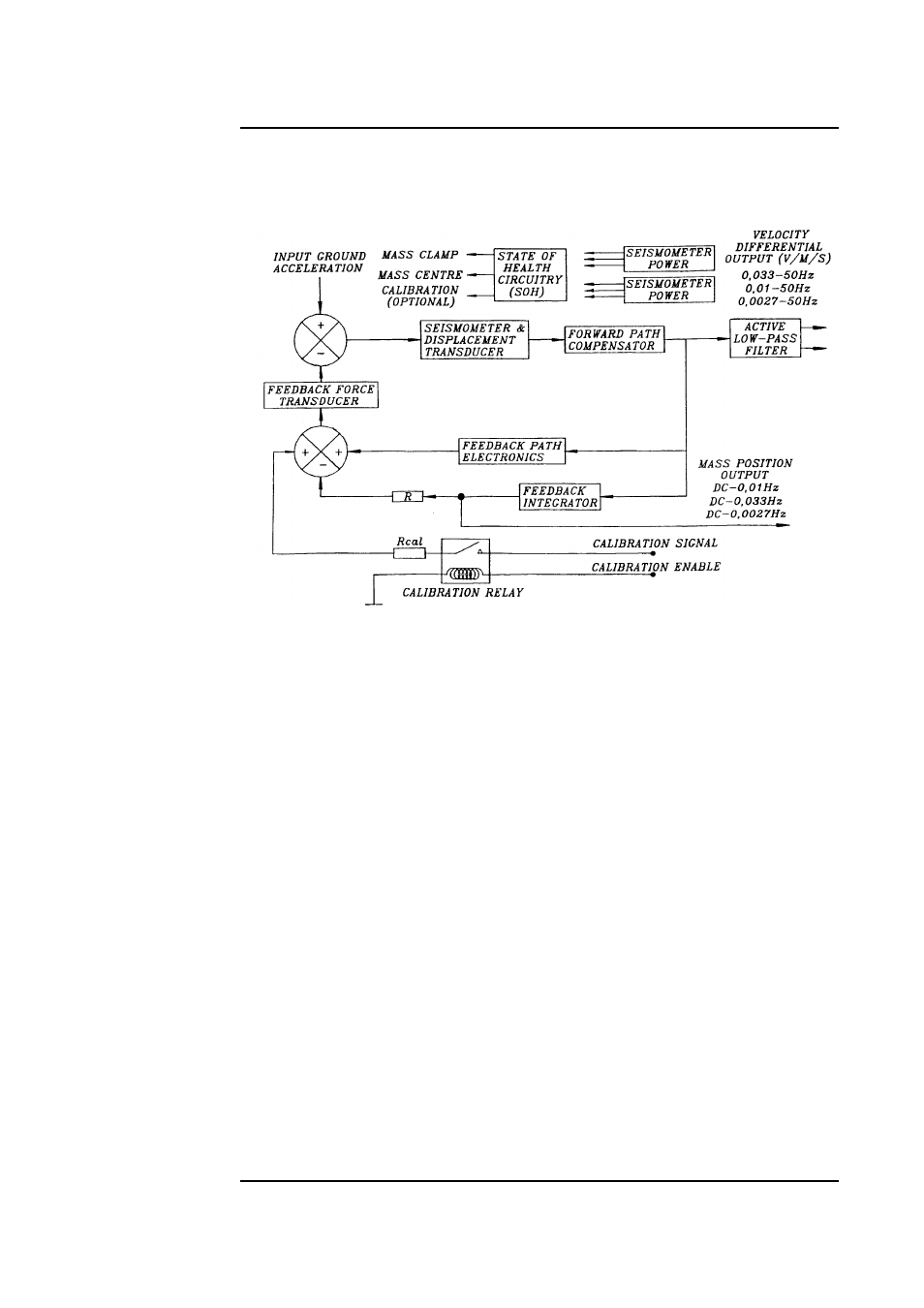
30 SEC, 100 SEC AND 360 SEC VELOCITY SENSOR
The block diagram of the velocity responsive seismometer is given below. This
block diagram is applicable to all the three types of velocity sensors.
The system velocity responses are defined by a transfer function identical to that
of a conventional long period sensor with a velocity transducer whose natural
resonant frequency is set at 0.033 Hz, 0.01 Hz or 0.0027 Hz and the damping z
at 0.707.
Similar to that of the hybrid system, the high frequency portion of the sensor
response is determined with a low pass filter. The corner frequency of this low
pass filter is specified by the user.
An output proportional to the ground acceleration is available from either of the
above described sensor frequency responses. In a feedback seismometer with a
displacement transducer it is essential to monitor the acceleration output as the
position of the displacement transducer is provided by this output. Under
normal operating conditions the displacement transducer needs to be in its
‘NULL’ ‘CENTRED’ or ‘ZERO’ position. The acceleration output (V/m/s
2
) is
also known as the sensor MASS POSITION as the displacement transducer is
always attached to the sensor inertial mass.