Gullco SAM CM-02-250 User Manual
Page 13
11
MOTOR CONTROL VARIABLE ADJUSTMENTS
Motor Control Variables are adjustable parameters that affect the core operation of the motor
control and its relationship with the motor. These variables are generic, regardless which
product/application specific micro-processor chip is installed.
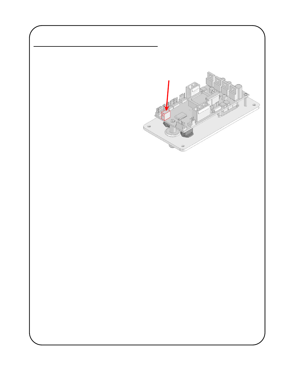
VR501
The Motor Control Variable Potentiometer is
located on the underside of the control circuit
board and is identified as VR501. A small flat-
bladed screwdriver is required for adjustment.
Fully counter-clockwise is the normal
operating location for this multi-turn
potentiometer. When in any position other
than fully counter-clockwise the control is in
programming mode, the round,
Preset Cycle
L.E.D.
in the bottom right hand corner of the
display will flash and the motor control will not
allow normal operation.
On the rare occasions that the Motor Control Variables require changing, it is usually necessary to
remove the control assembly from the equipment to gain access to the underside of the circuit
board and adjustments must be made with power applied to the control. Therefore, only competent
and technically trained personnel should perform this procedure. Turn the power off to the
equipment before removing the control assembly (by removing the four screws on the outer corners
of the face plate). Once the control assembly has been removed from the equipment, position it to
allow access to the front and back of the control. If it is necessary to disconnect any wiring from
any of the circuit board connectors, take the time to identify their respective connectors (as some
connectors are physically identical). The dc supply to the control must remain connected to
“CN50”.
To make changes to the Motor Control Variables, you must have access to the front and back of the
control assembly. Only when safe to do so, turn on the power to the control. With the power turned
on and the Auto-Enable/Manual Mode switch in the Manual Mode position, rotate the multi-turn
Motor Control Variable Potentiometer (VR501) clockwise to the variable (parameter) to be altered
(the Preset Cycle L.E.D. will flash on and off). The L.E.D. display on the front of the control will
show the number of the parameter on the display when the Forward/Neutral/Reverse switch is in
the Neutral position. I.e. “P. 1”, “P. 2”, “P. 3”, etc. To see the current value/setting of the variable,
place the Forward/Neutral/Reverse switch in either the Forward or Reverse position. To increment
the value/setting, place the Forward/Neutral/Reverse switch in the Forward position and press the
Cycle Push Button (located under the upper hole plug in the face plate). To decrement the
value/setting, place the Forward/Neutral/Reverse switch in the Reverse position and press the
Cycle Push Button. Pressing the Cycle Push Button briefly will increment/decrement the
value/setting by one, whereas keeping the Cycle Push Button depressed will scroll through the
values/settings until released. The speed display and or the individual L.E.D.’s will indicate the
chosen value/setting. When all of the program variables are set, rotate the multi-turn Motor Control
Variable Potentiometer fully counter-clockwise (the Preset Cycle L.E.D. will stop flashing). Turn the
power off and re-install the control assembly.
The values/settings of the variables are stored on the product/application specific micro-processor
chip. If the chip is replaced, the values/settings of the variables will need to be re-entered.