Groth 3011L User Manual
Page 4
3
The regulator must be sized to provide sufficient blanket gas to prevent the loss of tank pressure due to liquid discharge or
decreased ambient temperature. Table 4 lists the maximum flow capacity of the regulator for various blanketing gases. Actual
system flow will depend on supply system piping, tank connection piping and position of the internal orifice sleeve. Set pressure is
the pressure at which the regulator begins flowing when tank pressure is decreasing and stops flowing when tank pressure is
increasing.
This manual is intended to provide recommended procedures and practices for installation, operation, and maintenance of the
Groth MODEL 3011L, 3011H, 3011HP, 3041L, 3041H and 3041HP Regulators. Any standard procedures and practices developed
for a specific plant or process should supersede this manual. While this manual cannot cover all possible contingencies, following
these guidelines should provide safe, reliable regulator performance.
Note: Throughout this manual, the item numbers are listed in [ ] after the part description. These item numbers refer to the Bill of
Materials (Page 14) and various drawings of the regulator and its sub-assemblies (Figures 4 through 10). While the size and
appearance of the actuators differs between the 3011L and 3011H, the item identification and description of the components are
identical.
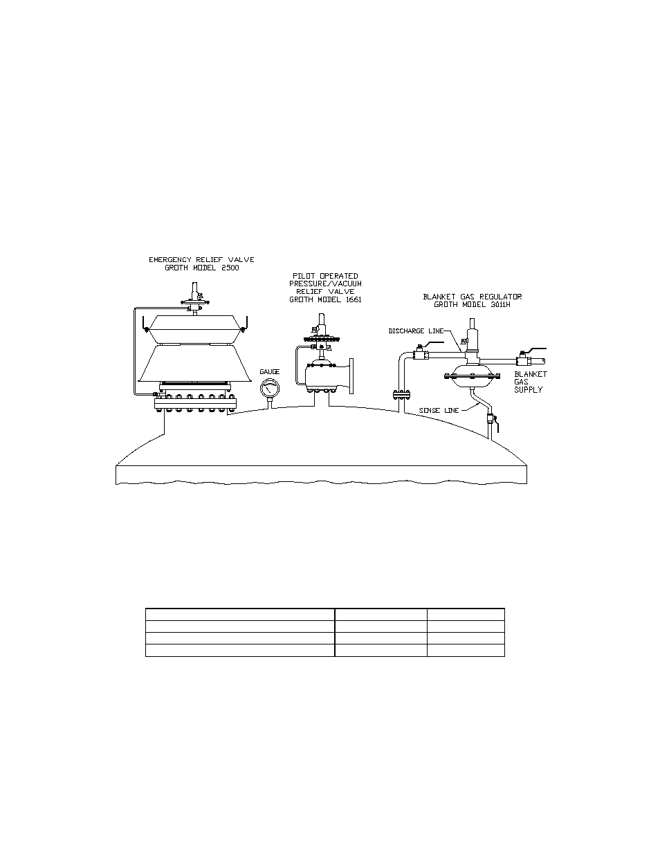
FIGURE 3: TYPICAL TANK INSTALLATION
TABLE 1: MODEL 3011/3041 SPECIFICATIONS
SIZE 1/2"
1"
Inlet/Outlet connection size
1/2"
1"
Maximum supply pressure
200 PSI
200 PSI
Actuator Housing MAWP
8 PSI
8 PSI