Testing and setting procedure – Groth 3011L User Manual
Page 15
14
Inspect and clean all diaphragm, gasket and seating
surfaces before assembling the actuator housing. Position
the upper actuator housing [4] on the body and secure with
(2) hex bolts [28] & lock washers [29] positioned 180° apart.
Torque the two bolts per Table 7. The body should be
oriented such that the outlet port aligns with the housing vent
hole. Measure the stroke of the piston. The stroke must be
a minimum of 0.180" for 1" BGR models and 0.150" for 1/2"
BGR models. Then position the actuator linkage assembly
into the housing and secure with the other (2) bolts.
WARNING: For 1/2" 3011H Models, install spacer [39]
between the actuator housing and linkage assembly.
Apply PTFE sealant tape around the inside hole pattern of
the upper actuator housing [4]. Position the actuator
diaphragm [42], the actuator gasket [35] and the lower
actuator housing [5] and insert hex bolts [31] hex nuts [33]
and lock washers [32]. Tighten uniformly in an alternating
pattern; refer to Table 7 for recommended torque.
WARNING: Replace bonnet vent or actuator housing vent
[24] if damaged or restricted. A plugged housing vent could
prevent the regulator from closing. This could cause an
over-pressure condition in the tank. A plugged bonnet vent
would prevent the release of supply pressure from the
bonnet. This could cause personal injury when
disassembling.
Invert the assembly in the vise. Install the upper piston
diaphragm [36], diaphragm retainer [8] and hex bolt [31] for
1" or button head cap screw bolt [30] for 1/2". Hold piston
with appropriate size wrench through inlet port while
tightening bolt. Install the bonnet adapter ring [9], spring
[34], spring buttons [10] and spring chamber [2]. Attach
bonnet to body with hex bolts [28] and lock washers [29] for
1" or socket head cap screws [43] and lock washers [29] for
1/2". Tighten bolts uniformly; refer to Table 7 for
recommended torque.
Thread set pressure adjusting screw [11] into bonnet until it
engages the upper spring button. Replace hex jam nut [27]
and cap [3].
TESTING AND SETTING PROCEDURE
1.0) Equipment
1.1) A high pressure air (or inert gas) supply system
capable of maintaining a regulated supply pressure of
0-300 PSI.
1.2) A low pressure air (gas) supply system capable of
maintaining sense pressure at 1/2" WC to 10 PSI.
Pressure may be controlled by a regulator or needle
valve and a small accumulator. If a needle valve is
used, it will require frequent adjustment because the
regulator consumes a significant volume of air when
operating.
1.3) A means of indicating or measuring air flow with a
capacity of approximately 30 SCFH.
1.4)
A means of soap bubble shell testing the assembly.
2.0)
Test Procedure and Acceptance Criteria
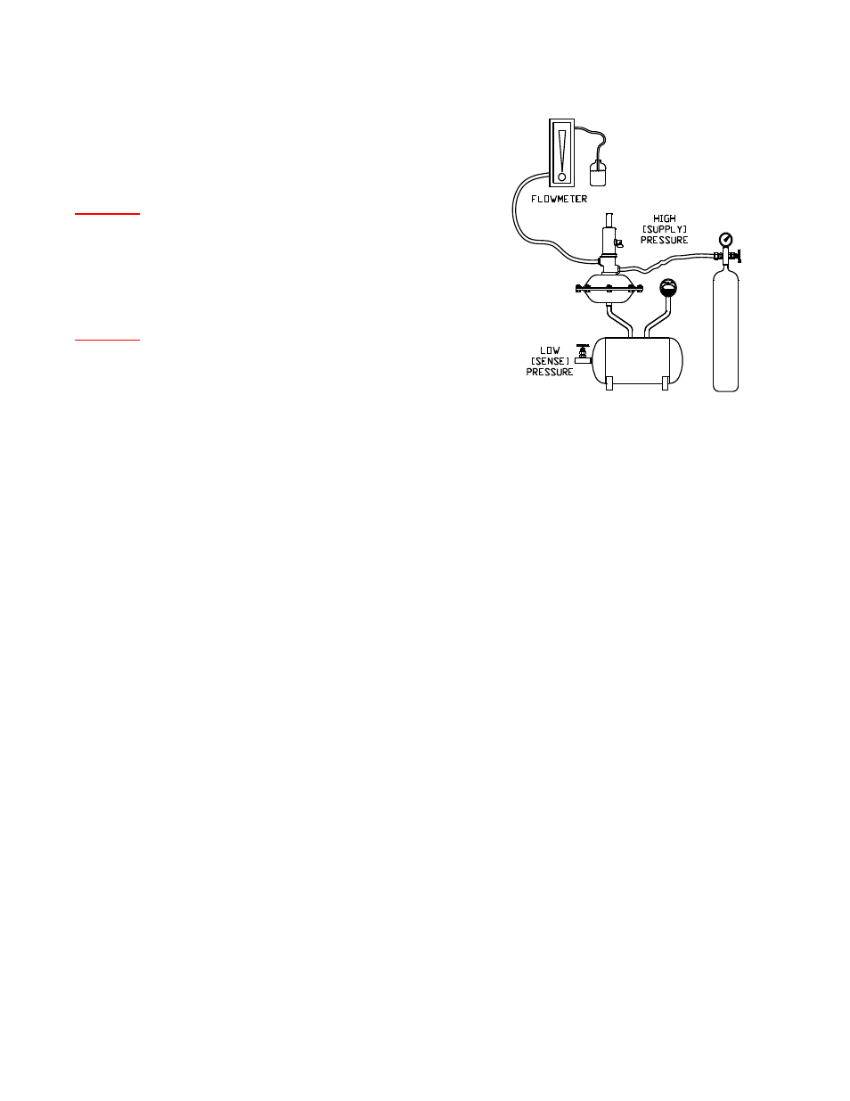
2.1) Connect the high pressure air supply to the regulator
inlet port. (See figure 3)
2.2) Connect the low pressure air supply to the regulator
sense port. (See figure 3)
2.3) Connect a reduced size manual shut-off valve to the
outlet port. (See figure 3 – Discharge line)
2.4) Connect a small diameter hose or plastic tube to the
inlet of the flow indicator or flow meter. Use a hand
held port cover to attach the flow meter to the
regulator outlet port. Never connect the flow meter
rigidly to the regulator unless the flow meter is rated
for full air supply pressure.
FIGURE 11: TEST SET-UP
2.5) Connect a small diameter hose or plastic tube to the
outlet of the flow indicating device so the end may be
immersed in a container of water.
2.6)
Close the outlet valve and set the supply air pressure
to the maximum available, but not greater than 300
PSI. Soap bubble test the entire assembly at this
pressure. Open the outlet valve and reduce the
supply until a minimum audible flow is observed.
2.7) Adjust the sense pressure to the specified regulator
set pressure. Adjust the adjustment screw [11] to
shut off (no audible flow). Now increase the sense
pressure to 2 times the specified set pressure or 1.5
times the specified tank MAWP, whichever is greater.
Soap bubble test the actuator housing.
2.8)
Increase the supply pressure to the specified system
pressure (100 PSI if not specified).
2.9) Slowly decrease the sense pressure and adjust the
adjustment screw until the air flow is 5-15 SCFH at
the specified setting. Lock the adjusting screw at this
setting.
2.10) While immersing the outlet tube in water, increase the
sense pressure until the regulator is bubble tight. If
this pressure exceeds the greater of 10% or 0.5" WC
above set pressure, examine the seat and O-Ring.
Do not adjust the regulator screw to improve bubble
tightness.
3.0)
Test Report Data
3.1) The following data should be recorded for future
reference:
Model, Tag & Serial numbers
Test
media
Body & Actuator shell test pressure