Disassembly – Groth 3011L User Manual
Page 12
11
DISASSEMBLY
WARNING: Before removing the regulator from the tank for
service, block and vent supply, discharge and sense lines.
Never attempt to remove the regulator from the line, or to
remove the spring bonnet or orifice sleeve locking screw if
the regulator is pressurized.
All service on the regulator may be performed with the
following common tools:
7/16" – 9/16" box end wrenches
1/4" or 3/8" open end wrench*
1/2"
socket
wrench
Adjustable
wrench
1/8"
Hex
wrench
*Wrench must be 8" long for 1/2" BGR or 12" long for 1"
BGR flanged units.
Thread a 1/2" pipe nipple into the sense port on the lower
actuator housing [5]. Use a vise and clamp onto the pipe
nipple. This makes a good holding fixture and provides
some degree of rotation while working on the regulator.
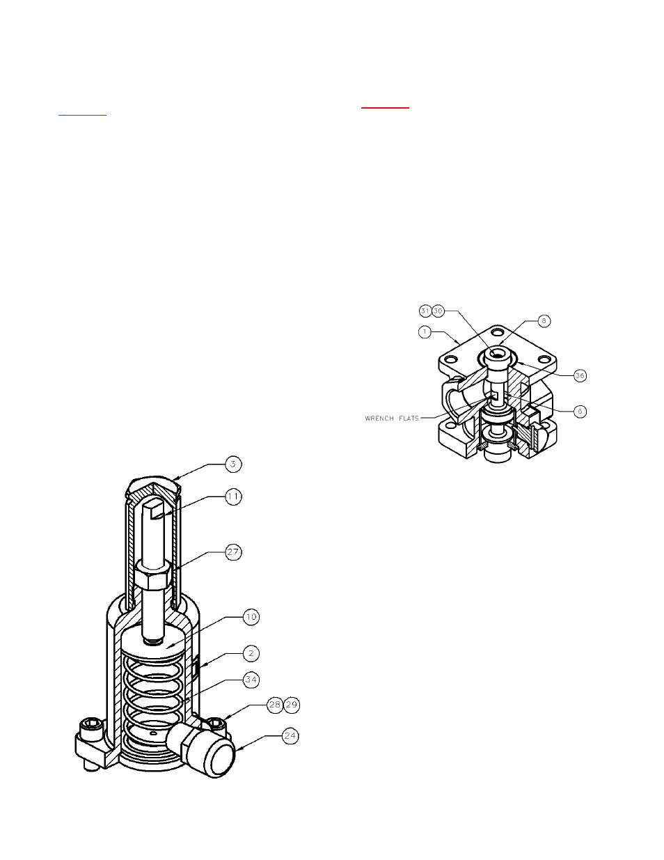
Remove the spring chamber cap [3] and loosen the hex jam
nut [27]. Turn the adjustment screw [11] counterclockwise to
completely relax the spring [34].
Remove the hex bolt [28] and lock washers [29]. Remove
the spring chamber [2]. Remove the upper spring button
[10], the spring [34], the lower spring button [10] and then
the bonnet adapter ring [9].
WARNING: Diaphragm actuator housing and regulator
body are exposed to the process vapor(s). Observe all
standard safety precautions as specified on Material
Safety Data Sheets for the product(s) that are in the
tank. These precautions apply both during removal of
the regulator from the tank and while repairing it.
Use a 3/8" (1/4" for 1/2" BGR) open-end wrench and
insert it through the inlet port to hold the piston [6] at
the wrench flats. Remove hex bolt [31] for 1" BGR
models or button head cap screws [30] for 1/2" BGR
models while holding onto the piston. Be careful not to
let the piston rotate during removal of the hex bolt.
The piston diaphragms [36] can be torn if care is not
taken. Remove the upper diaphragm retainer [8] and
the upper piston diaphragm [36].
FIGURE 5: PISTON/BODY ASSEMBLY
Remove the body/actuator assembly from the vise with
the pipe nipple connected. Invert the assembly and
clamp the body [1] in the vise.
Remove the hex nuts, lock washers, and hex bolts [33,
32 & 31]. Remove the lower actuator housing [5], the
actuator gasket [35] and the actuator diaphragm [42].
Insert a 1/2" socket wrench through the holes in the
actuator support plate [15] and remove the (2) hex
bolts [28] and lock washers [29] that retain the actuator
linkage assembly. Remove the linkage assembly and
set it aside. Remove the other (2) hex bolts and the
upper actuator housing [4].
Remove the piston guide ring [14], the guide ring O-
Ring [40] and the piston assembly from the body.
Remove the hex bolt [31] or button head cap screw
[30], O-Ring retainer [7] and piston diaphragm [36]
from the piston. Remove the stop lift ring [47] (1" size
only) the retaining ring [38] and the piston O-Ring [37].
Use care to prevent permanently expanding the metal
rings or scratching the surface of the piston.
FIGURE 4: SPRING CHAMBER ASSEMBLY