Groth 2000A User Manual
Page 12
12
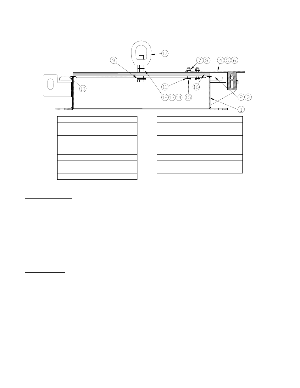
MODEL 2400A DISASSEMBLY & ASSEMBLY
ITEM DESCRIPTION
ITEM
DESCRIPTION
1 Body
10 Diaphragm
2
Pallet
11
Washer, 3/8", PTFE
3
Retainer Plate
12
Hex Nut, 3/4"-10 UNC
4
Hinge Arm
13
Lock Washer, 3/4"
5
Hinge Pin
14
Hex Bolt, 3/4"-10 UNC
6
Cotter Pin
15
Hex Bolt, 3/8"-16 UNC
7
Hex Nut, 3/8"-16 UNC
16
Weight Plate*
8
Lock Washer, 3/8"
17
Eye Nut*
9
Washer, 3/4", PTFE
* Not used on valves with low settings
2400A Disassembly
1. Read “Warning” sections on pages 4 and 6. Remove the valve from the tank.
2. Remove the cotter pin [6], from the hinge pin [5]. Pull the hinge pin through the body brackets.
Using the eye nut [17], or the edges of the pallet, lift the cover vertically. Set the cover on a short
length of pipe (minimum 6” high). This will elevate the retainer plate peripheral guides above the
table so they aren’t bent or damaged.
3. Place the assembly with the ¾” hex bolt in a vise, or use a wrench to hold the center bolt from the
bottom side. Loosen the hex nuts and remove. Lift the weight plate [16], pallet [2], and
diaphragms [10].
2400A Assembly
1. Prior to final assembly, verify that the body seat area is free of corrosion, damage or product build-up.
The pallet seat should be cleaned carefully, if necessary.
NOTE: If the seat is damaged it must be lapped using a perfectly flat ground metal disc and fine
grit emery cloth attached to the disc. Wipe seating surface clean before proceeding. Soft
goods should normally be replaced whenever valve maintenance is performed.
2. Reverse the steps of Disassembly, starting with the retainer and cover. If a diaphragm is an
elastomer, place it between the FEP diaphragm and the retainer plate. See Figure 3b.
3. Replace the cotter pin [6] if needed.
4. The valve should be tested on a pressure test stand to verify the settings and evaluate seat tightness
follow instructions on page 19. Mount valve on tank; see Installation on page 6.