Version 3-150 d – Grip Factory Munich GF-9 User Manual
Page 14
GF-9 Crane System Instruction Manual
Page: 13
Version 3-150 D
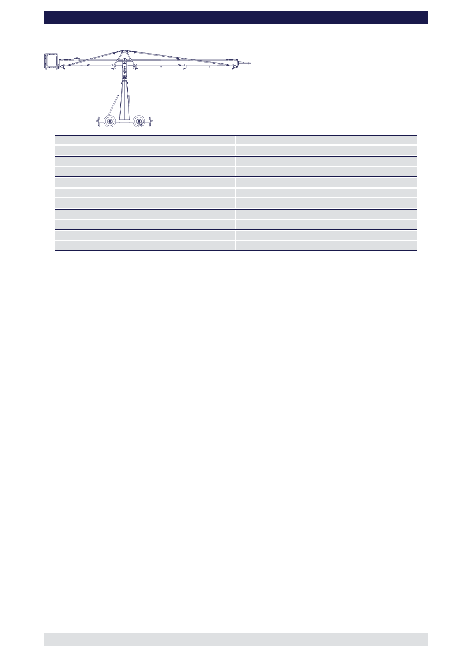
Front extension arms required
2 x 150 cm / 5’
Rear extension arm required
1 x 150
cm / 5’
Lift range
628 cm / 20’ 7”
Maximum remote bracket height
511 cm / 16’ 9“
Lift capacity
45 kg / 99 lbs
Counterweight required for max. load
84 kg / 184 lbs
Counterweight required to balance empty arm
8 kg / 17 lbs
Dolly weight
112 kg / 246 lbs
Crane weight (excluding dolly and weights)
101 kg / 222 lbs
Arm reach (pivot to camera head mount)
385 cm / 12’ 7“
Length of rear end (pivot to outside of bucket)
247 cm / 8’ 1“
Continue from § 10, page 5
11. Connect one of
the 150cm / 5’ sections to the middle section. Slip the connection
flanges into each other and secure them with the provided safety pin.
12.
Connect the 100cm / 3’3” sections to the 150cm / 5’. Slip the connection flanges into
each other and secure them with the provided safety pin.
13. Connect 2 rigging rods to the turnbuckles and secure with the safety pins.
14. Connect another 2 rigging rods to the first 2 and in turn connect these rods to the
rigging rod connectors on the last section and secure with the safety pins.
15. Adjust the turnbuckles until the rod are taut.
16.
Connect one of the 150cm / 5’ parallelogram rods to the middle section and secure it
with a safety pin.
17.
Connect the another 150cm / 5’ parallelogram rod to the first parallelogram rod and
secure it with a safety pin.
18. Connect the remote bracket angle adjuster to the end of the last section and secure it
with the provided safety pin.
Tip:
The angle adjuster has an integrated leveller. By turning it, the vertical plate
on the angle adjuster can be set to a perfect right angle. Correct setting of the angle
adjuster enhances the crane’s balance.
19. Insert the rod on the remote bracket angle adjuster into the parallelogram rod a
secure with the safety pin.
20. As required, attach the weight bucket or weight rod to the opposite end of the crane
by inserting the male flange into the female flange on the angle adjuster. Secure it
with the safety pin.
Tip:
The angle adjuster has an integrated leveller. By turning it, the vertical plate
on the angle adjuster can be set to a perfect right angle. Correct setting of the angle
adjuster enhances the crane’s balance. Level the weight bucket before loading any
weights
Before operation, all locking pins, locking screws etc should be inspected to ensure
that all assembly sections are securely fastened.